3GO模拟飞行网|3GO Cyber Air Force

 找回密码
 注册

QQ登录

只需一步,快速开始

搜索
查看: 18643|回复: 12

[资料]The F-15 Flight Control System

[复制链接]
发表于 2014-5-5 14:49:00 | 显示全部楼层 |阅读模式
本帖最后由 L0op8ack 于 2014-5-5 15:06 编辑

http://www.f15sim.com/?page_id=16
The F-15 Flight Control System
By Pete Garrison, Eagle Driver #2
    The philosophy of the Eagle design was primarily, "Let's get the performance, then we'll tame it."  The "taming" has been an exercise in flight control wizardry which burned a lot of midnight oil, but has produced for your pleasure a fighter with explosive performance that handles like a dream.  However, under all that finery dwells a rather caustic personality which is cloaked in the shroud of acronyms such as CSBPC (Control Stick Boost and Pitch Compensator), PRCA (Pitch and Roll Control Assembly), and PTC (Pitch Trim Compensator).
    I'm going to assume that you've had some basic exposure to the F-15 flight control system and know that it uses conventional hydro-mechanical ailerons and differential stabilator for roll control, collective stabilator for pitch control, and a rudder on each vertical for yaw control.  In addition, there is a dual-channel, high-authority, three-axis CAS (Control Augmentation System) superimposed on the hydro-mechanical system.  The CAS is utilized to shape aircraft response to pilot inputs, as well as provide three-axis damping and autopilot functions.  The CAS can also provide aircraft control in the event of a mechanical system failure.
    With this in mind, I'd like to break the control system into two elements - the basic hydro-mechanical system and the electronic system (CAS) - then further subdivide each and perhaps give you some insight as to why things are as they are.
Basic Hydro-Mechanical Control System
    Pitch Ratio - This device adjusts the amount of collective (pitch) stabilator deflection available for a given longitudinal stick motion.  The ratio is scheduled to produce essentially the same stick travel per "g" throughout the flight envelope.  Since the longitudinal feel system is just a simple spring cartridge, this then relates to a constant stick force per "g" (Fs/g) (about 4.25 lb/g).  It is scheduled by Mach number and altitude and does a rather good job; however, it won't quite cover the full range of aircraft and stabilator power and there is some scatter of the Fs/g, i.e., some mild increase in sensitivity during low altitude/high speed flight, and some decrease in sensitivity at low speeds.
    Pitch Trim Compensator (PTC) - Obviously, the airplane can be disturbed in pitch in several ways - speed brakes, transonic trim changes, flap extension, etc., so the PTC system was devised to relieve the pilot of the task of compensating for these things with large longitudinal stick motions.  In reality, it is an automatic series trim which senses that the pilot is beginning to compensate for a change in trim.  Remember, the Eagle flys at essentially a constant stick position for a given g.  If that stick position changes and the aircraft is not responding with the correct g schedule at 5.25lb/g, the PTC will move the stabilator in the direction to maintain the g schedule.  This is also true at 1 g and at any disturbance from 1 g which the pilot begins to compensate for will automatically be trimmed to maintain 1 g.  Since it is a "series" trim, the stick won't move perceptibly, the but the stabilator will.  It will continue to move to the limits of the PTC authority so long as the error signal between the stick position and the aircraft g schedule exists.  Another fall-out of this system then becomes obvious - as you change speeds, there is no requirement to trim the aircraft in pitch - viola!  "neutral speed stability" (at least with the gear up).  It's going to be new to some of you, but I predict you're going to like it.  No more frantically trying to keep up with trim during an A/B acceleration.  On the subject of trim, the stick grip trim feels absolutely conventional.  It simply puts a bias in the system, and it is not trimmed out by the PTC.  If you're one of those strong armed nuts who likes to fly around with a bag full of force on the stick 'ala Thunderbirds, be our guest.  It works fine!
    Roll Ratio Changer - The roll ratio changer is simply an effort to accomplish in roll what we do in pitch, i.e., maintain the initial roll response of the aircraft somewhat constant.  We use both ailerons and differential stabilator for hydro-mechanical roll control, and would generate some unacceptably high rolling accelerations, roll rates, and structural loads at high speed if we didn't back off the amount of roll control surface available with a given lateral stick command.  Even with the use of the roll ratio, the max roll rate of the Eagle scatters quite a bit; however, the time to bank to 90 degrees stays together pretty well.
    Aileron/Rudder Interconnect (ARI) - Most pilots have excellent instinctive response to pitch and roll, but stupid feet.  When the lateral acceleration has you pasted on the canopy rail, everyone has a pet "memory cue" to rely on, like "step on the hard rudder," "squeeze the ball in the middle," etc.  That may have been okay for "flying the hump," but it just won't do anymore in the fighter business.  We spent an awful lot of time trying to convince Hun and Phantom pilots that nature had intended that any maneuvering at high angles of attack must be done with the feet, but even then it didn't always work.  The ARI "beasty" in the F-15 in an attempt  to cure the "stupid feet syndrome" and put some logic back into "stick back, nose up" and "stick right, roll right"!  The business of stick right-yaw left has made many a fearless fighter pilot pale.  During rolling maneuvers, the F-15 has its share of adverse yaw at positive angles of attack and proverse yaw at negative angles of attack (primarily in the subsonic area, so the hydro-mechanical ARI is cut out during supersonic flight).  Therefore, we simply utilize the roll ratio changer to wash out the yaw producing differential controls at aft or forward stick positions and produce rudder in the direction of the roll at positive (aft stick) angles of attack and against the roll at negative (forward stick) angles of attack.  This is done to keep the adverse yaw from killing the roll rate at positive angles and prevent the proverse yaw from producing extremely high roll rates at negative angle of attack.  Remember, the F-15 has strong positive dihedral effect, which produces strong roll in the direction of yaw at all flight conditions.
    The full ARI is fine for the clean configuration; however, in he landing configuration, it's not so swift, particularly during the landing rollout with the stick held aft and attempting to put down that rising upwind wing.  All that would be accomplished would be very little lateral control and a hard rudder into the wind.  Take it from me, it's uncomfortable - so - on gear extension, we eliminate the lateral control washout with longitudinal stick position but retain the rudder deflection with lateral stick.  On touchdown, we also eliminate the rudder deflection with the lateral stick.  In other words, on the runway, we go back to conventional relationship of stick/rudder pedal to control surface.
    Rudder Authority - The F-15 has three different hydro-mechanical rudder authorities:
  • +/- 15 degrees of pilot input below 1.5 Mach number
  • +/- 5 degrees of pilot input above 1.5 Mach number
  • +/- 30 degrees for ARI input with the stick held full aft and full lateral inputs made

    The reason - high positive dihedral effect accompanied by very high rudder power generates too much roll due to yaw to allow the pilot the full 30 degrees of rudder on the pedals.  Steady-state, full-rudder sideslips would be impossible to control even though the rudder will not fully deflect as speed increases due to aerodynamic loads.  However, the full 30 degrees is required to handle the adverse yaw situation at some extremely high angle of attack flight conditions.
Control Augmentation System (CAS)
    The F-15 CAS utilizes series authority in all three axes.  This simply means that the primary surface actuators contain an electronically controlled input to the actuator which can move the surface without pilot control stick motion.  Although the CAS cannon move the actuator full stroke, the authority available can produce very large control surface motion.  Consequently, a hard-over could cause out-of-control or structural failure.  Since the pilot's capability to respond to this high authority is limited by his reaction time, the system contains an "automatic paddle switch" in the form of dual channels.  Two completely redundant channels are constantly compared to each other, and in the event of a failure of one channel, the entire axis shuts down.
    Pitch Channel - The pitch CAS channel detects a pilot pitch force command on the stick and converts this into an electrical command at approximately 3.75 lb/g.  As the aircraft begins to respond, g and pitch rate "feed back" against the command signal so as to maintain a given Fs/g and damping characteristic.  The hydro-mechanical system is continuing to function as previously described even though the series actuator is fine-tuning the pitch handling qualities through the CAS.  The prime interface between the pitch CAS and pitch hydro-mechanical is through the CAS interconnect servo which drives the PTC in the direction to keep the CAS series servo centered in its +/- 10 degree stabilator pitch authority.  The pitch CAS also incorporates a washout signal with angle of attack, so that the pitch series servo won't try to hold the stabilator up to the limit of its series authority during stall approaches.  By washing out the pitch CAS at high angles of attack, the stick forces and aircraft motion look the same pitch CAS on or off - i.e. - the nose gets heavy at the same speeds because the CAS cannot delivery the extra 10 degrees of CAS stabilator authority as would be dictated if the washout was not used.
    Roll Channel - The roll CAS channel attempts to fine-tune the roll performance.  Pilot lateral stick motion results in the hydro-mechanical differential stabilator and aileron deflecting and at the same time, the lateral force on the stick results in an electrical roll rate command signal.  The roll CAS attempts to satisfy the command through the series CAS authority of the differential stabilator (no CAS series authority on ailerons).  In addition, roll damping is provided through the same series authority.  The max CAS roll rate command is reduced above 1.5 Mach number to reduce the maximum roll rates at high supersonic speeds.
    Yaw Channel - The yaw CAS series servo authority provides yaw damping, which needs no further explanation, plus a couple of other items which do - i.e. - CAS ARI and turn coordination.  The CAS ARI does essentially the same job as the hydro-mechanical ARI except that it is scheduled by roll rate as a function of angle of attack.  It can operate subsonically or supersonically  if required, to keep the aircraft coordinated during rolling maneuvers.  It attempts to keep the lateral acceleration as close to zero as possible.  Since it has a series authority of +/- 15 degrees of rudder, it can add this 15 degrees to the 15 degrees available to the pilot through the mechanical linkage when on the ground (no feed back).  In the air, the feed-back loops will prevent the pilot from getting more than the 15 degrees hydro-mechanical deflection unless it's required to maintain zero side slip due to some aerodynamic asymmetry such as split flap, asymmetric external stores, etc.
    I hope this has cast some light on the why's of the Eagle's flight control system.  Happily, it comes together quickly after you start to fly, so relax and enjoy it!

 楼主| 发表于 2014-5-5 14:56:49 | 显示全部楼层
本帖最后由 L0op8ack 于 2014-5-6 00:23 编辑

MISC Panel Operation
misc_drawing.jpg
Roll Ratio Switch
AUTOProvides normal system functions
EMERGRemoves hydraulic pressure from the hydromechanical roll control system which causes the roll ratio to drive to a midrange and lock. Mechanical Aileron-Rudder Interconnect (ARI) is also disabled.
The Roll Ratio control is part of the F-15s lateral control system.Lateral stick motion positions the ailerons rudders and stabilators to provide roll control.
The ratio of aileron/differential stabilator deflectionto lateral stick motion (roll ratio) is adjusted automatically for differentairspeeds, longitudinal stick position and gear position.
This providesthe same roll response for a given stick deflection regardless of airspeed.
Aileron and differential stabilator deflection are washed out to prevent adverse yaw when longitudinal stick deflection is combined with lateral stick deflection.
At subsonic speeds, the roll ratio is reduced. With the landing gear down, full aileron/differential stabilator is available at any longitudinal stick position.
If UTL A and PC2A hydraulic pressures are lost or the roll ratio switch is in EMERG, the roll ratio system drives to mid-range and locks.
A spin recovery aid provides full lateral control authority, regardless of longitudinal stick position, when the yaw rate exceeds 60 degrees per second.
Full lateral authority will be discontinued when the yaw rate is less than 60 degrees per second.
The mechanical Aileron-Rudder Interconnect (ARI) adjusts the control system such that lateral stick motion results in varying rudder deflection dependent on longitudinal stick position.
With the control stick aft of neutral, lateral stick motion causes rudder deflection in the same direction as stick motion.
With the control stick forward of neutral, lateral stick motion causes rudder deflection in the opposite direction of the stick motion.
In addition, when the flaps are down, the amount of rudder deflection for lateral input is increased. The ARI is disengaged at supersonic speeds and on landing.
If the anti-skid system detects a malfunction or the landing gear circuit breaker is OUT, the ARI may remain engaged at wheel spin up, adversely affecting crosswind landing characteristics.
Turning the anti-skid switch OFF or PULSER will insure ARI disengagement. If UTL A and PC2A hydraulic pressures are lost or Pitch or Roll Ratio switch is in EMERG, the ARI is inoperative.
If the mechanical system is inoperative, the differential stabilators (through roll CAS) will provide lateral control for moderate manuvers including landing.

Landing and Taxi Lights
OFFLights are off.
LDG LIGHTIf the nose gear is down and locked through 73-107 or the landing gear handle is down (74-081 and up), the landing light is turned on.
TAXIIf the nose gear is down and locked through 73-107 or the landing gear handle is down (74-081 and up), the taxi light is turned on.
The landing and taxi lights are on the nose gear strut.
They are controlled by a toggle switch on the miscellaneous panel. The lights are off, regardless of switch position, on aircraft through 73-107 when the nose wheel is not down and locked, or on aircraft 74-081 and up, when the landing gear handle is in the up position.

Inlet Ramp Switch
AUTOThe AIC automatically controls the air inlet system. This is the normal position.
EMERGRemoves electrical power from the ramp and bypass door actuators,
causing them to move hydraulically to the emergency (ramps locked up and bypass door closed) position. If hydraulic pressure fails, airloads will force the ramps and bypass door to the emergency position.
An inlet ramp switch for each inlet is on the miscellaneous control panel.
The switch is lever locked, and has positions of AUTO and EMERG.
Anti-Skid System
NORMThe anti-skid is on when the gear is down. However, illumination of the ANTI-SKID warning light activates the brake pulser system and ARI is disengaged with the gear down.
PULSERTurns off normal anti-skid protection, turns on the ANTI-SKID and MASTER CAUTION lights, and activates the brake pulser system. The ARI is disengaged with the gear handle down.
OFFTurns off the normal anti-skid and brake pulser systems. Disengages ARI with the gear handle down.
Operational information on this page taken from TO 1F-15A-1, Change 1 – 15 August 1984

 楼主| 发表于 2014-5-5 14:58:43 | 显示全部楼层
本帖最后由 L0op8ack 于 2014-5-6 00:24 编辑

ILS/TCN Panel Operation


TACAN (Tactical Air Navigation) SYSTEM
The TACAN system functions to give precise air-to-ground bearing and distance information at ranges up to approximately 300 miles (depending on aircraft altitude) from an associated ground or shipboard transmitting station.
It determines the identity of the transmitting station and indicates the dependability of the transmitted signal.
When operating in conjunction with aircraft having air-to-air capability, the A/A mode provides line of sight distance between two aircraft operating their TACAN sets 63 channels apart.
Up to five aircraft can determine line of sight distance from a sixth lead aircraft in the A/A mode, provided their TACAN sets are set 63 channels apart from the lead aircraft.
The limit of operation is four times the distance between the lead aircraft and the nearest aircraft. The lead aircraft will indicate distance from one of the other five, but it cannot readily determine which one.
Before operating in the A/A mode, the frequencies used by each aircraft must be coordinated.
TACAN information except in A/A mode is presented on the horizontal situation indicator (HSI), the attitude director indicator (ADI), and the head-up display.
In A/A mode, both distance and bearing are received if cooperating aircraft (such as refueling tanker aircraft) have bearing transmission capability.
TACAN CONTROLS
The controls for TACAN operation are on the ILS/TCN control panel on the left console, on the steering mode panel on the main instrument panel, and on the HSI.
The controls on the ILS/TCN control panel are the function selector knob, the volume control knob, the channel selector knob and the XY switch.
The controls on the steering mode panel consist of the steering mode knob. The controls on the HSI are the course set and the heading set knob.
Function Selector Knob
The function selector knob is a three-position rotary knob used for selecting TACAN modes of operation. The mode positions are marked A/A, T/R and REC.

Function Selector Knob
T/RTACAN receives bearing signals from the TACAN ground station, and in addition, the TACAN interrogates the TACAN ground station to establish distance from the aircraft to the ground station. The bearing and distance information is displayed on the HSI.
RECTACAN receives bearing signals from the TACAN ground station for bearing display on the HSI, and also for steering display on the ADI and HUD. TACAN distance readout is shuttered on the HSI.
A/ATACAN interrogates other aircraft which contain a TACAN in the A/A mode and is tuned 63 channels apart from the channel setting of the interrogating aircraft. Bearing and distance information is received from a cooperating aircraft if it has bearing transmission capability. If the cooperating aircraft is not equipped with bearing transmission equipment, only distance information is received and the HSI No. 1 bearing pointer will rotate clockwise at 30 degrees per second.
Volume Control Knob
The volume control knob is used to turn the tacan on and off and for volume adjustment of the station identity tone signal.
Channel Selector Knob
The channel select or knob provides for selection of 126 TACAN        channels. The control consists of an outer knob used to select the units digit of the channel counter (0 to 9) and an inner knob used to select the tens and hundreds digits (00 to 12).
XY Switch
The XY switch is a toggle-type with positions of X and Y. Placing the switch to the X position provides capability for 126 channel operation. Placing the switch to the Y position adds an additional 126 channel capability to the TACAN system.
Operational information on this page taken from TO 1F-15A-1, Change 1 – 15 August 1984
 楼主| 发表于 2014-5-5 14:59:54 | 显示全部楼层
本帖最后由 L0op8ack 于 2014-5-5 15:13 编辑

Engine Control Panel Operation

ENGINE CONTROLS AND INDICATORS
Engine Master Switches
Two guarded engine master switches are on the engine control panel.
Placing either switch to ON (with electrical power available), directs power tothe fuel transfer pumps.
Each switch directs power to its corresponding FTIT indicator and opens is corresponding airframe mounted engine fuel shutoffvalve.
The engine master switch must be ON before the corresponding enginecan be coupled to the JFS.
Placing the switch OFF decouples the engine from the JFS.
If engine control/essential power is not available, placing anengine master switch OFF will not shut off its airframe mounted engine fuelshutoff valve.
Engine Start Fuel Flow Switches (F100-PW-100)

The engine start fuel flow switches, on the right console provide improved starting performance under certain ambient temperatures and elevation.
The switches have positions of HIGH, AUTO and LOW and are spring loaded to thelever-locked AUTO position.
HIGH        Provides a rich fuel flow for starts and overrides the automatic sequence.
AUTO        Provides a lean fuel flow during normal start.  Fue flow is lean until 30 seconds after the main generator comes on the line then        automatically increases 100 pph (rich).
LOW        Fuel flow will drop approximately 100 pph when this position is selected.

EEC Switches (F100-PW-100)
The L and R EEC (engine electronic control) switches are located on the enginecontrol panel and provide power to the EEC.  The switches have two positions,ON and OFF.
ON        Turns on power to the EEC.
OFF      Turns off ECC supervisory control of UC.  Exhaust nozzle remains closed with gear handle down.
ENG CONTR Switches (F100-PW-220)
The L and R ENG CONTR (engine control) switches are located on the enginecontrol panel and provide power to the DEEC (digital engine electroniccontrol).  The switches have two positions, ON and OFF
ON        Turns on power to DEEC for normal engine control.
OFF        Turns of DEEC and transfers engine control to secondary mode (hydromechanical).  Afterburner inhibited, engine rpm reduced to 80% max, and exhaust nozzle will remain closed with gear handle down.
JFS Starter Switch
The jet fuel starter switch is on the engine control panel located on the rightconsole.  It has positions of ON and OFF.
During engine start, the JFS isautomatically shut down after both engines are started; however, it can beshut down at any time by placing the switch to OFF.
JFS Ready Light
The JFS ready light is on the engine control panel located on the right console.The light indicates the JFS is ready to be engaged.  The light goes out whenthe JFS shuts down.
Generator Control Switches
Two generator control switches, one for each generator, are on the enginecontrol panel.  They are two-position toggle switches with positions of OFFand ON.  
The switches are lever-lock type and must be raised up before theyare moved to a new position.
Emergency Generator Control Switch
The emergency generator control switch, on the engine control panel, is athree-position toggle switch with positions of AUTO, MAN and ISOLATE.  The switch is electrically held in the ISOLATE position.
AUTO        Provides automatic activation of the emergency generator if either or both main generators are inoperative, both transformer-rectifiers fail, or either or both main fuel boost pumps fail.
                  After TO 1F-15-764, provides automatic shutdown of the emergency generator 30 seconds after the first main main generator comes on the line after a ground start without external power.
                 On all aircraft, for starts with external power the emergency generator will not operate as long as external power is connected.
MAN        Provides manual activation of the emergency generator.
ISOLATE   Restricts the emergency generator to powering the emergency fuel boost pump and arresting hook and provides power from the emergency/essential 28 volt DC bus to the emergency air refueling switch to open the slipway door.
                   On F-15C 83-0035 and up and F-15D 83-0049 and up, the engine rpm indicators are also powered in this position.
                   In the event of a complete electrical failure, an attempt to restore the emergency generator may be made by cycling the switch to ISOLATE and back to MAN.
External Power Control Switch
The external power control switch, on the engine control panel, controls application of external power to the aircraft electrical buses.  An externalpower monitor will prevent faulty external power from being connected to the aircraft system.
NORM        Allows the aircraft electrical buses to be energized by external power if no aircraft generators are operating.
RESET        Will establish external power if it is not on the line. It is spring-loaded to NORM.
OFF        Disconnects external power from the aircraft.

Please note that the drawing at the top shows the engine control panelas it would be found in an F-15C powered by the F100-PW-100 engine.  
The panel in my F-15C is for the F100-PW-220 engine.  I've included both textsections for clarity and completeness.
Operational information on this page taken from TO 1F-15A-1, Change 1 - 15August 1984
 楼主| 发表于 2014-5-5 15:00:28 | 显示全部楼层
F-15 Hydraulic System
By ROBERT S. ANDREWS/Senior Engineer, Hydraulic Design
The F-15 Hydraulic System incorporates some of the latest hydraulic design concepts from the standpoint of safety, survivability, and maintainability. McDonnell has been able to incorporate these many design improvements because of the high learning curve obtained from design and operation of the highly successful F-101 Voodoo and F-4 Phantom II.
The Hydraulic Systems consist of three independent systems: Power Control 1 (PC-1), Power Control 2 (PC-2), and Utility. PC-1 and PC-2 systems power the primary flight controls and the Utility system supplies all other requirements, plus back-up for stabilator longitudinal and roll control, aileron roll control, and rudder directional control. Hydraulic power is available to adequately and safely maintain control for flight and landing with any one of the three systems operational.
INTERFACE OF SYSTEMS
The block diagram shows the various subsystems in the "A" and "B" circuitry of the PC-1, PC-2, and Utility systems. In the Utility system, the "A" circuit lines are primarily on the left side of the aircraft and the "B" circuit is primarily on the right-hand side. This improves survivability from a gunfire standpoint.
Since any one of the three hydraulic systems can maintain a supply of hydraulic pressure to the control system, it is obvious, as you refer to the illustration, that the crisscross of hydraulic supply to the flight controls from left and right engine driven pumps, through RLS circuitry and switching valves, gives multiple redundancy of hydraulic supply to the F-15 primary flight control components. Here is what will happen during several emergency situations:
  • When all electrical power is lost,
    control is maintained with ailerons
    and differential stabilator for roll,
    stabilator for pitch, and two rudders.
  • When either PC hydraulic system
    plus the Utility hydraulic system, and
    all electrical power are lost, control is
    maintained with ailerons on one wing
    and differential stabilator for roll, stabilator
    for pitch, and one rudder. (If PC-2 and Utility are lost, the Control Stick Boost and Pitch Compensator will be inoperative.)
  • When all mechanical controls are
    lost, control is maintained by the
    Control Augmentation System driving
    the differential stabilator for roll and
    pitch, and both rudders.
  • When both PC-1 and PC-2 hydraulics are lost, control is maintained with the Utility hydraulic system supplying power to all primary flight controls.
HYDRAULIC PUMP
For ease of maintenance, the F-15 pump was designed as a plug-in type. The intake, outlet, and case drain fluid flows are directed to the spline-drive end of the pump where they pass through quick disconnect couplings. These connect the pump to an aircraft mounted manifold which has rigid tubing attached, allowing the pumps to be installed and removed without disconnecting hoses and tubes. Doing away with hoses eliminates the possibility of chafing and there are fewer leakage points. Self-sealing checks were incorporated to prevent line drainage during replacement. The pump also incorporates fast-response compensator shutoff to lower hydraulic system pressure spikes. Basic system accumulators found in most aircraft have been eliminated (these are high replacement items and can be responsible for introducing air into a hydraulic system).

FILTER PACKAGE
Each of the three systems (PC-1, PC-2, and Utility) has a single filter module which incorporates pressure and return filters, system relief valves, pressure switches, pressure transmitters, and pump outlet check valves. As a result, there is one module and one door per system, simplifying servicing. All pressure and return elements are non-collapsible at 4500PSI ΔP and are in one size and type (15 micron absolute with an approximate 8 gram dirt capacity) for commonality and good logistics control. The filters have self-sealing checks incorporated to prevent line drainage, and there are delta-P indicators at the bottom of the bowl to reveal a dirty element. The bowls must be removed to reset the indicator and the bowl cannot be replaced without an element inside. The bowls feature self-locking ratchets, and are non-interchangeable pressure-to-return to assure murphy-proof maintenance. The relief valve is a fast-response type backing up the fast-response pump compensator allowing elimination of accumulators. The pressure filter is non-bypass while the return filters are dual purpose. They filter the system return oil (bypass) and the pump case drain (non-bypass). This allows the pump case drain (which carries particles from the hardest-working most wear-producing component in the system) to have a large, high-dirt capacity filter with no danger of particle recirculation to accelerate pump wear. This also prevents wear particles from a failing Utility pump from contaminating the second Utility system pump.
RESERVOIRS
Each of the three F-15 bootstrap type reservoirs incorporates reservoir level sensing (RLS). RLS works on the principle that a leak developed in the aircraft will cause the reservoir level to sink. As the level decreases, RLS sensing mechanically operates a valve which shuts off half the system (designated "A"). If this stops the leak, the reservoir level will stop sinking and the other half of the system (designated "B") will be retained.
On the other hand, if the leak �continues, the reservoir will continue to deplete until a second valve shuts off the "B" half of the system. When "B" shuts off, the "A" system returns, reactivating one-half of the system. This is accomplished by mechanical linkage between the "A" and "B" shutoff valves. Leaks in the pump or filter circuit are not protected by reservoir level sensing. However, as you can see, RLS improves the survivability of the aircraft.
The gaging system on the F-15 reservoirs is also unique as the gaging is temperature compensating to allow for volume increase or decrease due to oil temperature changes. Automatic overflow occurs if the reservoir is overfilled, preventing reservoir damage.
  SWITCHING VALVES
Another new type of hydraulic component found in the F-15 is a "switching valve." Four of these are used to further improve the survivabil-ity of the primary flight control systems. Two switching valves are in the aileron circuit; two others are in the tandem stabilator/rudder circuits.
  These valves allow the normal operating pressure from the "B" RLS circuits of both PC-1 and PC-2 to pass directly through the switching valves to the left and right ailerons, to one side of each tandem stabilator, and to each rudder. Should a "B" circuit lose pressure for any reason (leak, pump failure, etc.), the switching valves will move to a test position to assure that the system downstream of the switching valve is intact. If system integrity is verified, the Utility system will be switched into the downstream flight control actuators. This test position prevents loss of Utility oil should the break be downstream of the valve.

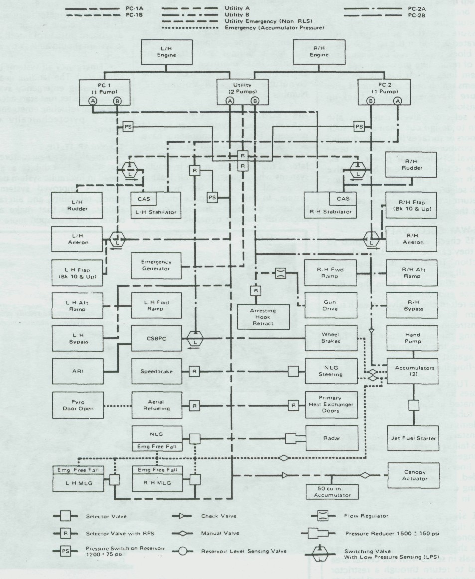
F-15 Hydraulic System Diagram
HYDRAULIC SELECTOR VALVES
In the F-15, the hydraulic selector valves have a design feature called return pressure sensing (RPS) which was incorporated to improve hydraulic system reliability. Selector valves with RPS will not operate if there is a leak in the selected lines or in the return line to the first check valve. This prevents the pilot from switching into a failed hydraulic circuit where the oil would be directed overboard, thus losing the entire system, or half a system if the failure was in one of the RLS branches.
Return pressure sensing blocks the pressure to the solenoid pilot-operated section of the selector valve. The block is achieved by sensing the loss of return line pressure in the subsystem lines which have failed. Subsystems which must be operated after failure have emergency back-up provisions.
In selector valves, care was also taken to design out "man traps" such as doors or surfaces that are hydraulic-ally positioned open or closed upon removal of electrical power. An example is the F-15 speed brake valve which remains in a full trail position (both selected lines become common to return if electric power is removed from the aircraft).

ONE-WAY CHECK VALVES
F-15 check valves are designed so that they can be installed in only one direction. Therefore, it is impossible to install one backwards during maintenance. The secret lies in the different size end fittings.
The return check valves in each subsystem have been installed as far downstream as possible, just prior to entering the main return trunk line. This gives the maximum line protection against losing reservoir oil from back-flow into a leak in a return line.


COIL TUBES
Hoses and most swivels have been eliminated in the F-15 through use of coil tubes. Some of the common problems of the past (including chafing, installation in a twist which accelerates failures, cross-connection which is dangerous, and weepage through hose liner imperfections) have been avoided. In addition, swivels with rotating dynamic seals are at a minimum in the Eagle.


DUAL SHAFT SEALS
F-15 flight control and engine inlet components use dual external dynamic shaft seals. This design utilizes two seals in series with the center area vented to return through a restrictor which reduces system internal leakage in event of a first stage seal failure. The second stage atmospheric seal is normally subjected to return pressure but is capable of withstanding full pressure should the first stage seal fail. This allows increased seal life and component survivability as the first stage dynamic seal is lubricated on both sides. Should the first seal fail, the second seal can act as a back-up.


FITTINGS
The F-15 plumbing uses a new, permanently swedged fitting in some locations, eliminating many potential inline tube connector leak points. The tube connectors used at valves, and at remaining inline connectors, are of the latest design, stay tight, and require less maintenance. (The DIGEST took a closer look at the Dynatube fittings in Volume 22, Number 3, 1975.)
AIR PROBLEMS
Air in hydraulic systems is an age-old problem. The F-15 components have been specially designed to eliminate this possibility. The canopy accumulator is the only unit in the hydraulic systems where pressurized air leaking by a seal can enter the hydraulic system. In this case, space dictated the use of a smaller standard accumulator with a single dynamic seal. Air problems such as overflow or bursting of reservoirs, excessive bleeding after emergency operations, and cavitated pumps with momentary loss of system pressure have been minimized during design of the Eagle.
Here are some of the applications that minimize on-board air problems.
  • Basic system accumulators have
    been eliminated.
  • Dual vented seals are used in
    components which have air chambers.
    Typical of these are jet fuel start
    accumulators, arresting gear cylinder,
    and canopy counterbalance actuators.
    Dual seals allow the air to be vented
    overboard instead of into the hydraulic
    system should air leak by a dynamic
    seal.
  • Emergency air systems have been
    eliminated. The landing gear, brakes,
    and steering emergency systems use
    oil from the jet fuel start accumulator.
    The aerial refueling emergency system
    uses a pyrotechnically operated
    system.


TO WRAP IT UP ...
With all these new features, we feel that the F-15 exhibits a giant step ahead in hydraulic system design. The results - improved system maintenance, reliability, and aircraft survivability. Things that make a product better, and a weapon more effective.


 楼主| 发表于 2014-5-5 15:01:04 | 显示全部楼层
A Broad Brush Look at...
The F-15 Hydro-Mechanical Control System
By B.P. "PERRY" HOFFMAN/ Senior Engineer. Flight Control Section, Avionics Engineering Laboratories
At the beginning of any aircraft design program, the customer specifies his requirements and desires. In the case of the F-15. handling qualities were rigidly spelled out by the USAF: "The aircraft must meet or exceed Level II requirements throughout its operational envelope without the aid of electronic augmentation. " Military Specification M1L-F-8785B(ASG) defines all the details of flying qualities sought in an aircraft. For the sake of this article, the following brief definitions should suffice:
  • Level I - Flying qualities clearly
    adequate for the mission Flight Phase.
  • Level II - Flying qualities ade-
    quate to accomplish the mission Flight
    Phase, but some increase in pilot work-
    load or degradation in mission effec-
    tiveness, or both, exists.
  • Level III - Flying qualities such
    that an aircraft car. be controlled safely, but pilot workload is excessive or mission effectiveness is inadequate, or both. In short, this means that the basic hydro-mechanical control system must be such that a pilot can complete an air-superiority mission without a bunch of electronic boxes doing it for him.

    To better explain Level II handling, an F-4 Phantom (in contrast with the F-15) is incapable of meeting Level II requirements throughout its maneuvering envelope with SAS (or Stab Aug) operating.
Within this article we'll explain how the controls of the F-15 Eagle satisfy this requirement. In later issues of the DIGEST we'll go a little deeper into the system to shed some light on the role of electronics in increasing control capabilities to Level I handling qualities.
  
Fig. #1: Flight Control System Hydraulic Diagram
CONTROL STICK BOOST/PITCH
COMPENSATOR

Since the Eagle's flight controls are designed with a fighter pilot's needs in mind, the end result is a blend of specification requirements and pilot desires. Any reference to the similarity between a conventional century series fighter control system would be difficult. It's obvious that both contain control sticks and control surfaces: however, in the F-15 it's what's in between that makes the difference.

The part that's "in between" is what we call the "CSBPC," or Control Stick Boost/Pitch Compensator. This device is the "brains" of the F-15 mechanical control system and contains two major assemblies known as the "Pitch/Roll Channel Assembly" (PRCA), and the Aileron Rudder Interconnect (ARI).

Since any aircraft responds differently to a given control surface input, depending upon the flight condition and extent of maneuvering, considerable sophistication must be employed within the mechanical control system to assure uniform response to pilot commands. The PRCA and ARI units help the basic hydro-mechanical controls provide the maneuvering capabilities and handling qualities required to satisfy the Level II specifications.

Since the applications of the PRCA and ARI in the Eagle are quite involved, we won't discuss them in detail at this time. Instead, we'd like to consider the total hydro-mechanical control system now with coverage of individual axis and electronic portions in forthcoming issues of the DIGEST.


HYDRAULICS
The F-15 control system is powered by three separate hydraulic systems: Power Control One (PC-1) driven by the left engine. Power Control Two (PC-2) driven by the right engine, and a Utility system which contains two pumps, one on each engine. Each system is provided with a switchover valve which senses system return pressure. If pressure falls below a pre-selected value, required pressure is regained through a switch to another system.

Referring to the hydraulic system block diagram (Figure 1), you can see which hydraulic system powers which control system actuator. The PC-1 system powers the left side of the aircraft plus both stabilator actuators. The PC-2 system powers the right side of the aircraft plus redundant power to both stabilator actuators. The Utility hydraulic system is a backup system and        can provide power to the entire control system. The PRCA and ARI receive their hydraulic power from the Utility system with PC-2 as a backup. What this all adds up to is a system that can be safely flown and landed after a total loss of any two of the three hydraulic systems.

LONGITUDINAL CONTROL SYSTEM
At first glance the Longitudinal Control System (Figure 2) seems to be a conventional system, but as you look at component locations some interesting and important differences become evident.

The feel trim actuator, located in the aft fuselage of most aircraft, is located below the control stick in the F-15. This reduces the amount of linkage, thus reducing control stick dead-band, and lessens overall applied stick force.

Added safety is also obtained should there be a linkage separation downstream of the PRCA. If a separation does occur, a "fly-by-wire" capability is provided by the electronics and the pilot will still have positive feel at the stick. With a manual system such as installed in the F-15, a pilot may not even realize he has a linkage separation since the aircraft will fly and feel the same with or without the problem.

The Pitch/Roll Channel Assembly (PRCA) provides variable mechanical advantage of the pitch control system as a function of airspeed system data.

It also aids in controlling stabilalor de-flection to eliminate the difference between commanded and actual load factors. This feature compensates for trim changes due to such things as speedbrake or flap extensions, external store separations, and aircraft speed changes. The combination of feel trim, variable mechanical advantage, and series trimming gives the pilot, as near as possible, a constant stick force per G and keeps the stick pretty well in the same place in the cockpit throughout the flight. The linkage friction within the PRCA is carefully controlled to reduce control stick breakouts. The feel trim actuator location and shortened linkages to the PRCA and its low linkage friction provide the pilot with smooth, light control stick breakout forces. The PRCA output is hydrauli-cally boosted, eliminating any feeling by the pilot ot excessive frictions downstream of the PRCA. In addition, the hydraulic boost provides a shear force for chips and other foreign objects.

Outside of the PRCA the pitch linkage is fed to a "mixer" linkage where it is combined with roll inputs. These give the stabilator inputs reflective of either pitch or roll. The F-15 stabila-tors arc used collectively tor pitch and differentially for roll.


Fig. #2: Flight Control System - Longitudinal Controls
LATERAL CONTROL SYSTEM
As you review the design of the Lateral Control System (Figure 3) you'll find some similarities to what we've just covered in the longitudinal system. The feel trim actuator is located below the control stick, and it is there for the same reasons mentioned for the pitch trim actuator.

Variable mechanical advantage of the Lateral Control System is provided by the Roll Channel of the PRCA as a function of airspeed data. The stick-to-aileron ratio is also reduced as a function of longitudinal stick position. As angle of attack is increased, deflections are decreased for a given stick deflection. This eliminates the need for a pilot to remember to roll only with rudder during high angle air combat maneuvers. As the stick-to-aileron ratio is decreasing, the ARI is supplying information to increase rudder deflection.

Roll output of the PRCA is hydraulically boosted for the same reasons as is pitch output. The mixer linkage, referred to earlier, receives a lateral input which is transmitted to the ailerons and as differential signals to the stabilators.

A safety spring is provided, allowing continued roll control operation should one side become totally jammed. The aircraft can be safely flown and landed with one aileron and differential stabilator control. Aileron surface power is supplied by conventional hydraulic actuators.


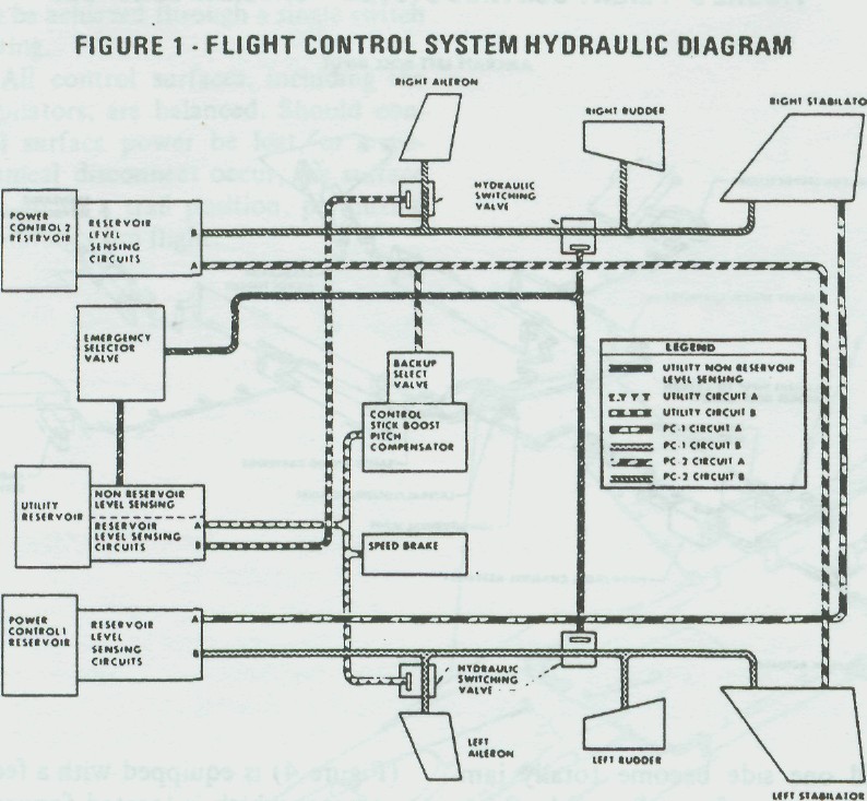
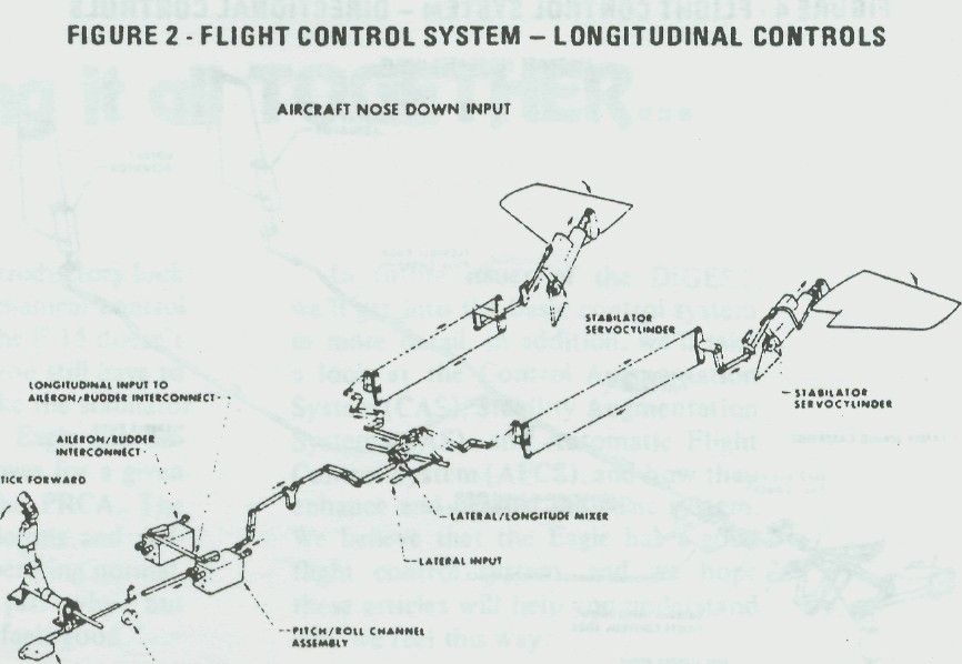
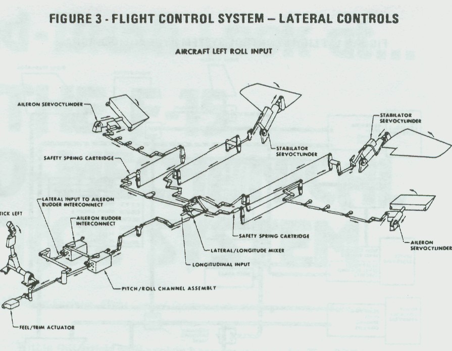
Fig. #3: Flight Control System - Lateral Controls
DIRECTIONAL CONTROL SYSTEM
The Directional Control System (Figure 4) is equipped with a feel trim actuator which is located forward and between the rudder pedals. A safety spring cartridge permits continued aircraft control and nosewheel steering in the event the rudder linkage jams. Should a linkage jam occur, mechanical control is no longer possible: however, pedal forces can be sent to the CAS electrically which will give "fly-by-wire" control of the rudders.

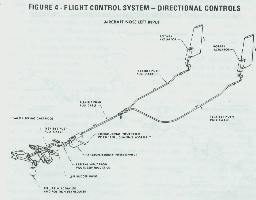
Fig. #4: Flight Control System - Directional Control
Mechanical pedal inputs are supplied to the ARI box. scheduling rudder control as a function of lateral and longitudinal inputs. The output of the Aileron Rudder Interconnect repositions a flexible ribbon which moves two rotary actuators, deflecting the rudder control surfaces.

EMERGENCIES
Should hydraulic power to the PRCA be lost, or if the pilot elects to select emergency modes of either roll or pitch through cockpit switching, the PRCA positions itself to a preset ratio, locks up. and allows adequate control for sate flight and landing. In this configuration, the functions of the PCRA and ARI packages could literally be replaced by simple bellcranks.

In addition, there is dual trim mechanization which prevents runaway trim. Takeoff trim for pitch, roll, and yaw can be achieved through a single switch setting.

All control surfaces, including the stabilators, are balanced. Should control surface power be lost, or a mechanical disconnect occur, the surface         will go to a trail position, permitting continued trim flight.
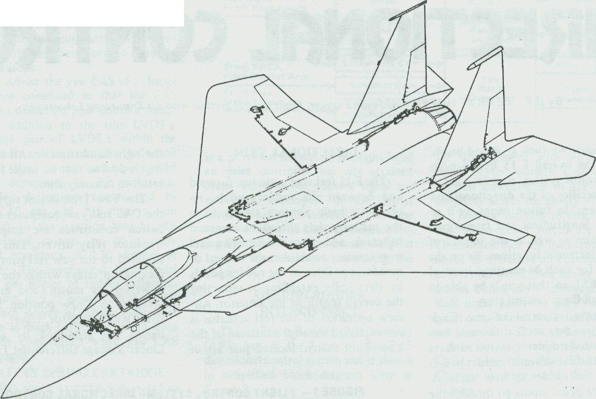
  Fig. #5: Flight Control System Linkage Illustration

Putting it all together...
We'll wrap up this introductory look at the Eagle hydro-mechanical control system by saying that the F-15 doesn't do anything by magic: you still have to pull on the pole to make the stabilator move. However, in the Eagle the distance the stabilator moves for a given input depends upon the PRCA. The same applies to the ailerons and rudders. If everything is operating normally you won't know just why, but you'll find that "it just feels good."

In future issues of the DIGEST, we'll get into the basic control system in more detail. In addition, we'll take a look at the Control Augmentation System (CAS). Stability Augmentation System (SAS). and Automatic Flight Control System (AFCS). and how they enhance and parallel the basic system. We believe that the Eagle has a good flight control system, and we hope these articles will help you understand why we feel this way.

 楼主| 发表于 2014-5-5 15:01:39 | 显示全部楼层
F-15 Flight Control System
Part II - Directional Control
By B.P. "PERRY" HOFFMAN/ Senior Engineer. Flight Control Section. Avionics Engineering Laboratories
Last issue we took a "Broad-brush" look at the overall F-15 hydro-mechanical control system; now let's get into the specifics of the directional control system. In future issues we'll review the longitudinal and lateral control systems as well as the impact of various electronic functions. Be on the lookout for each bi-monthly issue of the DIGEST so that you'll be able to get the full flight control story.

Directional control of the Eagle conies from two vertical tins and two synchronized rudder control surfaces (Figure 1). Conventional rudder pedals position the rudder control surfaces. All rudder pedal inputs go through the Aileron Rudder Interconnect (ARI) box. a part of the Control Stick Boost/ Pitch Compensator. The ARI combines rudder pedal signals with functions of roll and pitch, providing turn coordination over a wide range of pitch and roll maneuvers.

Input authority to the rudder control surfaces in production F-15 aircraft is 15 degrees maximum. Lateral control slick inputs are scheduled within the ARl box for a maximum surface deflection between zero and 30 degrees depending upon longitudinal slick position.

The ARI output is fed via flexible push-pull shafts to each of the rudder control surface actuators. The F-15 rudder power actuator is a part of the rudder hinge, allowing a smooth, streamlined surface with no linkage to wear or jam.

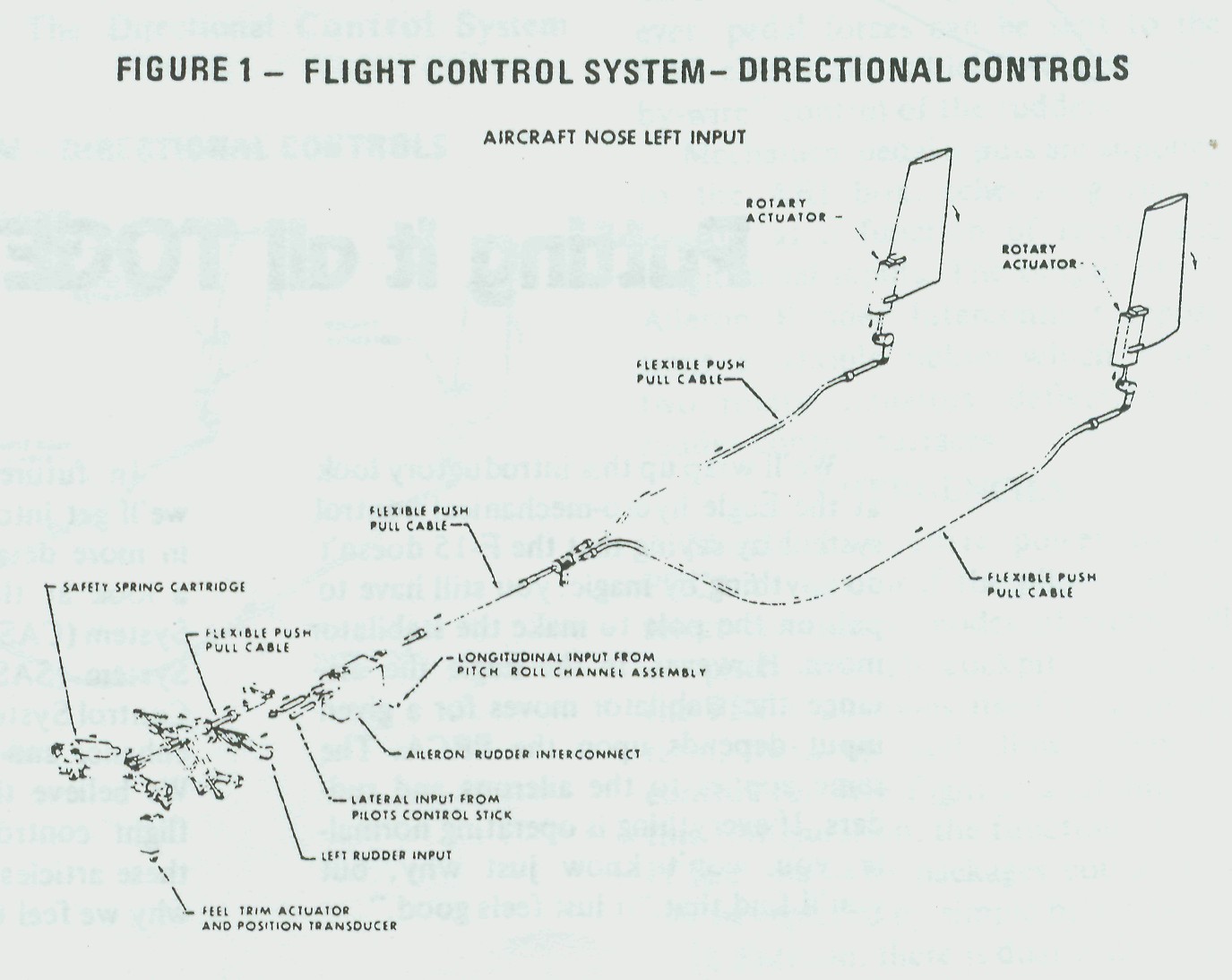
Fig. #1: Flight Control System - Directional Controls
DIRECTIONAL TRIM
The F-15 feel trim actuator, forward and between the rudder pedals, receives its basic position signals from the rudder pedals through a common bellcrank and torque tube. The feel trim actuator establishes the neutral or zero force position of the rudder pedals by electrically extending or retracting the overall length of the actuator. Aircrew operation of the feel actuator is accomplished through actuation of the Yaw Trim switch, located just aft of the right-hand throttle. All trim circuitry is dual so that no single failure can result in runaway trim.

The Yaw Trim switch signal goes to the CAS roll/yaw computer where the switch commands are amplified by transistor relay drivers. This output is supplied to the yaw feel trim actuator, picking up relays within the actuator, powering its motor, and driving the actuator to a new position. Simultaneous with actuator travel, electrical signals are generated by a pair of Linear Voltage Differential Transformers (LVDT). These signals are fed back to the CAS roll/yaw computer and are used for three distinct functions. The signals:

� Establish actuator neutral when the takeoff-trim button is held depressed.� Limit actuator travel through use of voltage level detectors within the CAS roll/yaw computer to prevent driving the trim actuator into its mechanical stops.

� Advise the yaw CAS of a change in trim command so that the CAS doesn't defeat the pilot-inserted trim.

In addition to the trim LVDT's. another pair of LVDT's within the feel trim actuator measure deflection of the "feel" springs, and supply pedal force commands to the yaw CAS. Rudder deflections commanded by the CAS can add �15 degrees with respect to the position held by the mechanical system, up to a combined maximum of �30 degrees of rudder. The mechanical input pedal force per degree of rudder deflection amounts to 9.75 pounds on the pedal for each degree of rudder deflection. Twice as much rudder per pound force can be commanded when yaw CAS is engaged.

SAFETY SPRING CARTRIDGE

A safety spring cartridge is provided so that, in the event of jammed linkage, pedal forces can still be applied allowing CAS control of rudder operation. This provides an excellent "fly-by-wire" rudder system allowing safe return to the Eagle's nest. This also permits continued use of the nose-wheel steering system with a jammed rudder link. The same applies in the event of a linkage separation: CAS can again supply the pilot pedal commands to the rudder.

RUDDER PEDAL LIMITER

A rudder pedal limiter has recently been added to the rudder pedal torque tube. At Mach 1.5 or greater, a discrete signal from the left-hand air inlet controller actuates the pedal limiter actuator, physically restricting movement of the torque tube and pedals thus limiting rudder surface deflection to no more than 5 degrees. This prevents excessive rudder-induced rolls in a flight regime where roll/yaw coupling is a potential hazard. If the right-hand air inlet controller has not attained Mach 1.5 and the discrete signal has not been developed, or the limiter actuator has not extended to close the Maximum Extend Limit switch, a warning light illuminates to advise the pilot to use caution when operating the rudders.
AILERON-RUDDER
INTERCONNECT

The Aileron-Rudder Interconnect (ARI) box is the heart of the F-15 directional control system and is shown in simplified block diagram form in Figure 2.


Fig. #2: ARI Block Diagram
Starting at the upper left corner of the diagram, yaw input from the pilot's pedals is fed directly into a summing linkage and out to the rudders. Since this function is a straight-through linkage arrangement with no hydraulic boost at the output, rudder linkage friction downstream of the ARI can adversely affect the ability of the rudder control surfaces to return to neutral when pedal forces are relaxed. This means that the maintenance man needs to eliminate all possible sources of friction within flex cables and bell-cranks during any maintenance action. Roll input from the pilot's stick and pitch output from the Pitch/Roll Channel Assembly (PRCA) harmonize the rudder output through the Yaw Ratio Controller, the Plus/Minus Ratio Changer linkage, and the summing linkage.

The Flaps Down shift valve modifies the schedule allowing more rudder, sooner, with flaps down than is available through the flaps up schedule. Looking at the graph (Figure 3), note that with flaps up and 10 degrees nose-up stabilator. you can expect 6 degrees of rudder per inch of lateral stick (two inches of left stick equals 12 degrees of left rudder). Likewise, with flaps down and 8 degrees of nose-down stabilator, you'll get 3 degrees of rudder per inch of lateral stick (two inches of left stick equals 6 degrees of rightrudder).

The Booster Servo at the roll input prevents rudder pedal commands from being fed back into the lateral control system. Coupled to the Booster Servo is the Full Stroke Pressure Limit valve which keeps the Booster from physically overloading the ARI structure as the ram reaches full stroke and simultaneous pedal inputs are applied.

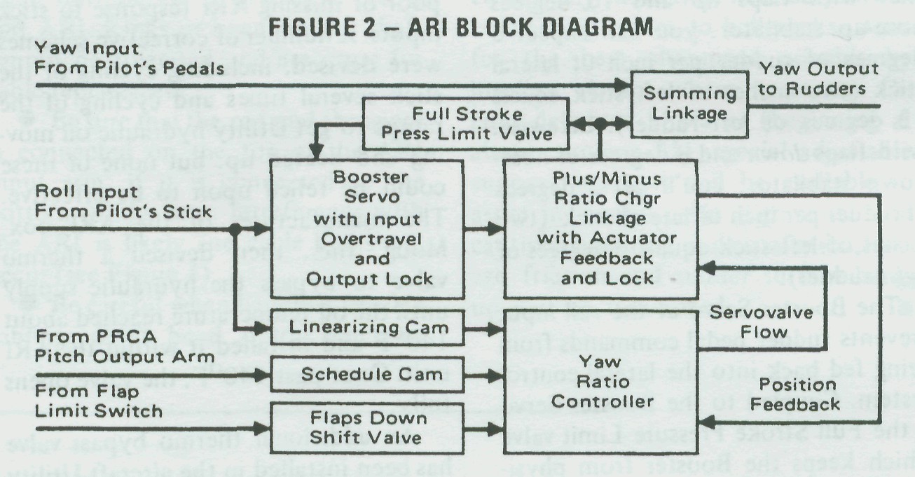
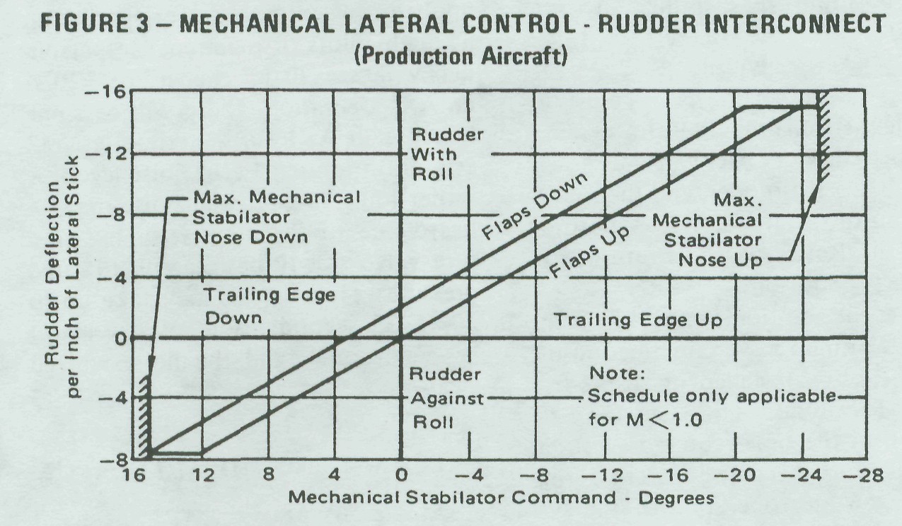
Fig. #3: Mechanical Lateral Control - Rudder Interconnect (Production Aircraft)
Since no ARI functions are required with the aircraft supersonic, a hydraulic shutoff valve located in the PRCA Pitch Ratio Controller turns off the supply pressure to the ARI unit when the aircraft reaches Mach 1. Rudder pedal commands are still available, as are the 15 degree CAS commands.

The Rapid Shutoff valve is actuated by the anti-skid wheel spin-up signal. Since we don't want the rudder to be controlled by lateral stick during cross-wind landings, lateral stick inputs to the rudder are turned off at ground-roll speeds of 50 knots or greater. The maintenance technician can duplicate this during preflights. While holding lateral and longitudinal stick inputs, note the rudder deflections, place the Anti-Skid switch to OFF. and the rudder should rapidly return to the trim position. Reselecting Anti-Skid should return the rudder to its deflected position within 25 to 35 seconds. You can get the same results by turning the Roll or Pitch Ratio switches to EMERGENCY. ARI will shut down, neutralizing the rudder, and the rudder will return to its deflected position when the Ratio switch is returned to the AUTO position.

A recent addition to the ARI is the Rapid Warm-up valve contained in the -17 ARI box installed in all production F-15 aircraft. The need for a reduction in the time required to attain ARI operation became apparent during the first winter operation of the system in St. Louis. On several occasions aborts and near-aborts were blamed on poor or missing ARI response to stick inputs. A number of corrective schemes were devised, including cycling of the stick several times and cycling of the ramps to get Utility hydraulic oil moving and heated up, but none of these could be relied upon to be effective. The manufacturer of the ARI box. Moog, Inc.. then devised a thermo valve to bypass the hydraulic supply until the oil temperature reached about 140�F and installed it within the ARI unit. Once past 140�F, the valve opens fully.


An additional thermo bypass valve has been installed in the aircraft Utility hydraulic supply just prior to entering the PRCA to help speed the warming of oil during aircraft engine operation (this thermo bypass valve does not apply during external power operation). Though pilots or maintenance personnel will see little change in PRCA or ARI operation, there will be some increase in ARI turn-on time, as well as a definite increase in noise levels. A rather loud, low-pitched noise may be heard due to the input reducing pressure valve slowly building up to rated pressure. Though this may take up to 30 to 35 seconds, don't worry about it; it's normal, and the noise will go away.MECHANIZING THE ARI OUTPUT
At the output of the ARI. mechanical push-rod linkages are replaced with a flat steel ribbon riding on steel balls within a flexible housing. You may be familiar with similar cables used in some throttle systems. This unique system of linkage connects the single output of the ARI individually to each of the rudder actuator control valves.

The control valves, operating from Utility hydraulic power, provide a rotary motion rather than the conventional extension or retraction of a hydraulic ram. Because of this design, the actuator requires no additional bell-cranks or other linkages to change motion direction. Each actuator forms an integral part of the rudder hinge: the actuator is a self-contained unit and positions the rudder control surface in response to pilot pedal commands

through the ARI. and electrical commands from the automatic flight control system (CAS).

If input linkage separation should occur, a pair of centering springs will return the input control valve to detent but yaw CAS commands of up to 15 degrees may be initiated through pilot pedal inputs allowing safe flight home. Electrical commands from the yaw CAS are received by an electro-hydraulic servo valve which in turn ports hydraulic pressure to the CAS piston. The CAS piston repositions the actuator control valve sleeve with resultant main actuator motion. Electrical feedback signals are generated by the CAS actuator Linear Voltage Differential Transformer, establishing a position authority on the surface. If a fault occurs anywhere in the CAS system that results in one rudder moving 3 degrees more than the other, yaw (and roll) CAS will automatically disengage.

MAINTENANCE CONSIDERATIONS
Conventional maintenance procedures apply to the directional control system, these are covered in the technical order. However, flexible shafts and cables require special care.

� Be especially careful when working with the flex shaft transmitting pitch information between the PRCA and ARI. Kinks or bends in this shaft cannot be tolerated and are cause for cable replacement.

� Be sure that the rod-end (bearing) is connected on the top of the ARI input arm; if it is connected to the bottom of the arm. interference with the ARI is likely and cable kinks will occur (see Figure 4).

� Be careful when handling flexible cabling; don't bend it too much or twist it any more than necessary. When connecting cables to bellcranks, strive for the best alignment possible by juggling clamps where necessary. On later delivered airplanes (beginning at about airplane 51), special adjustable support brackets will be available to assist in careful cable alignment. With cautious handling and installation linkage friction and rudder surface hangup will be minimized.


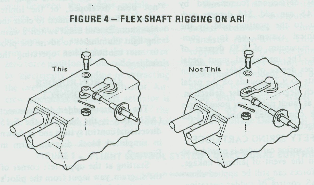
Fig. #4: Flex shaft rigging on ARI

 楼主| 发表于 2014-5-5 15:02:12 | 显示全部楼层
F-15 Flight Control System
Part III - Lateral Control
By B.P. "PERRY" HOFFMAN/ Senior Engineer, flight Control Section, Avionics Engineering Laboratories
Our last article dealt with the F-15 directional control system; now let's dig a bit deeper, progressing to the lateral control system. Lateral (or roll) control in the Eagle is obtained from simultaneous deflection of conventional ailerons located on the outboard section of each wing and differential stabilators. The amount of aileron/differential stabilator deflection per inch of lateral stick movement is controlled by the Pitch Roll Channel Assembly (PRCA),with scheduling based on both the output of the PRCA pitch boost servo (longitudinal stick position) and airspeed. The net effect is a proper blend of control deflections required for maneuvering throughout the aircraft envelope, and yet the pilot is given approximately the same feel no matter what the flight condition might be. Let's see how some of these requirements are mechanized.

LATERAL TRIM
Referring to Figure 1, follow the lateral linkage from the control stick to the lateral feel trim actuator. Note that the actuator is mounted in parallel with the overall control linkage. This is just a simple way to say that the system linkages are not shortened or lengthened; the trim actuator merely moves the total system.

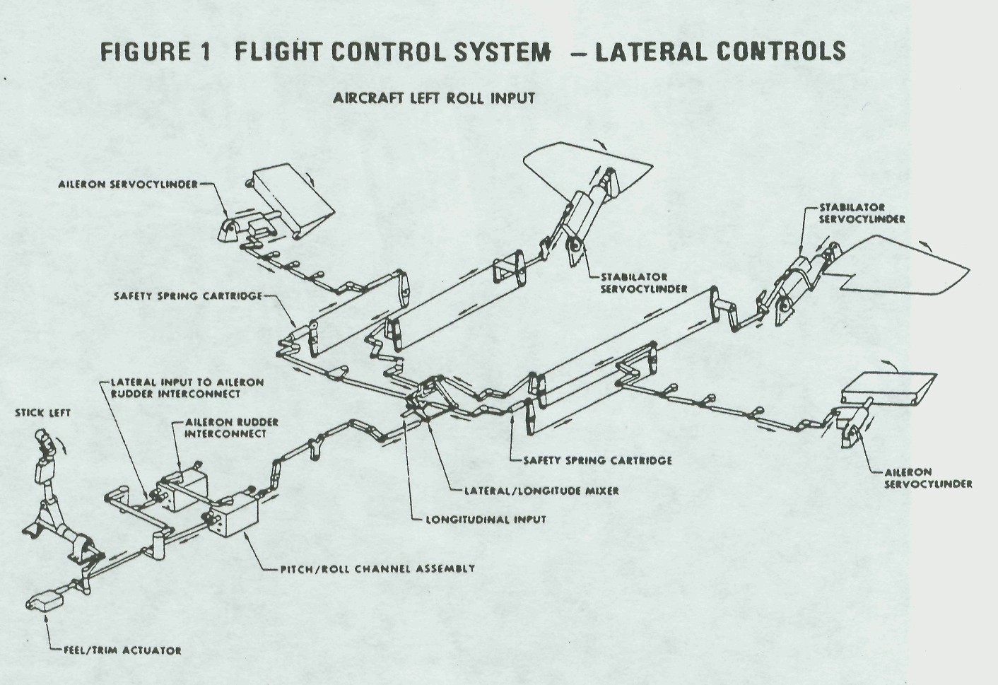
Fig. #1: Flight Control System - Lateral Controls
The feel trim actuator performs two equally important tasks: it establishes the zero force position of the control stick and provides the pilot with an artificial feeling of maneuvering stick force. The zero force or "hands-off-stick" position may be varied as the pilot requires by activation of the stick grip button. The trim motor may also be repositioned through operation of the takeoff trim button which drives the actuator to a preset neutral position, streamlining the control surfaces.
  Simultaneous with actuator travel, electrical signals are generated by a pair of linear voltage differential transformers (LVDT).
These signals are used by the Control Augmentation System (CAS) computers, where they are compared in a preset voltage level detector which turns the actuator off when the. proper level is reached. Another level detector stops the trim actuator at neutral if the takeoff trim button is held depressed.

Outputs from these level detectors are supplied to the takeoff trim indicator light logic in the CAS computers. When this logic sees the same voltage level from all three channels, (roll, pitch, and yaw), the takeoff trim light illuminates, indicating to the pilot that his surface controls are properly positioned for takeoff. These LVDT signals serve yet another function in advising the CAS roll channel of changes in trim commands so that the CAS doesn't defeat pilot-inserted trim. Lateral artificial feel force is provided to the pilot by dual spring gradients within the actuator. For the first inch of lateral stick travel, the force is 5 pounds (plus a 1.0 pound breakout); the gradient then drops to 3.67 pounds per inch of additional stick deflection. The dual spring gradient helps reduce lateral stick sensitivity around neutral. The LVDT signals and CAS circuits are dual redundant, providing a fail-safe operation in which the system shuts down to prevent runaway trim.

ROLL LINKAGE
As it leaves the lateral feel trim actuator, the linkage takes two paths. The first path travels to the ARI on the right-hand side of the airframe. As we discussed in Part II of this series, this input supplies the lateral intelligence to the ARI. The second path continues down the left side of the aircraft to the PRCA which is the "brains" of the F-15 mechanical control system. Figure 2 is a block diagram of the PRCA and shows the data flow within the roll channel of the PRCA.

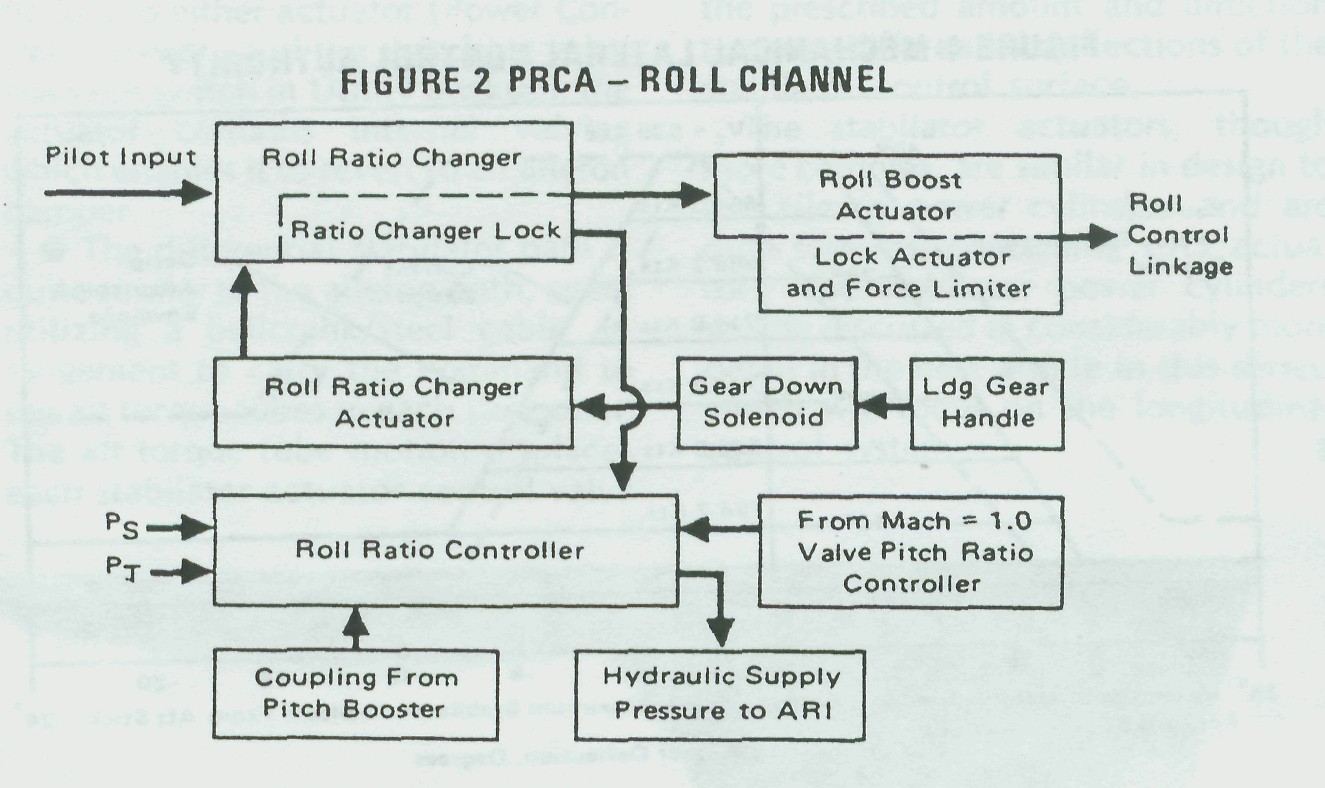
Fig. #2: PRCA - Roll Channel
Roll Ratio Changer -- The roll ratio changer, within the PRCA, contains the dual mechanical linkage required to vary the stick-to-aileron/differential stabilators gearing at a ratio of 4:1. Figure 3 explains how a parallelogram ratio changer does its work.


Fig. #3: Simplified Ratio Changer Diagram
The dotted lever 1 pivot D is fixed to the PRCA frame while its pivot E varies with the position of the roll ratio changer actuator. Lever 2 has its pivot C fixed to the PRCA frame while pivot A attaches levers 2 and 3 together.

Diagram I shows the ratio changer actuator at maximum ratio as indicated by distances D to A and E to C being identical. Pilot stick inputs to point A displaces the output B by the same amount; that is, a 1:1 ratio. In diagram II, note that the ratio changer has been fully extended, placing pivots E and C over one another. Stick inputs to point A can rotate the linkages about E and C with only a small amount of output displacement for a ratio of 4:1. Diagram III shows an intermediate ratio. In this case, pivot E of the ratio changer actuator can be called upon to vary the ratios as dictated by the air data information fed to it, or by longitudinal control system position.

Presuming you've digested at least a part of that, let's press on. Within the ratio changer section, you'll find a ratio lock. This drives the ratio changer mechanism to the failed ratio in event of a loss of hydraulic supply pressure. In addition, the pilot may select the emergency mode to isolate a suspected malfunction. He does so by placing the Roll Ratio switch to EMERG(ency) which removes hydraulic pressure to the roll ratio channel of the PRCA. The roll ratio repositions itself to about one-half ratio in emergency, or 10� of aileron plus 3� differential stabilator which is more than adequate for normal flight and safe return to base. During emergency operation of the roll channel of the PRCA, the Master Caution light and Roll Ratio telepanel light will illuminate warning the pilot of a problem. Lateral control stick inputs into the PRCA during the transition time are quite heavy
since the actuator is in the process of locking. However, after the short time required to lock, lateral control stick forces settle down to about twice that of a normal operating system. When the Roll Ratio switch is again placed in AUTO(matic), and the hydraulic supply pressure is available, normal system operation is restored.

Roll Ratio Controller/Roll Ratio Changer Actuator � The ratio controller and ratio changer actuator may be considered at the same time since the actuator simply provides the muscle for the ratio controller. The ratio controller receives pitot (Pt) and static (Ps) air inputs from the left hand probe. A cam-operated servo-mechanism controls hydraulic pressure to the roll ratio actuator, repositioning the ratio changer linkage to a new value. Figure 4 illustrates that both air data and longitudinal position affect the ratio controller. Longitudinal stick inputs to the roll ratio controller are the result of mechanical coupling to the roll ratio controller shaft from the PRCA pitch channel boost actuator. The combination of the air data and longitudinal inputs reposition the ratio changer and vary the control stick-to-aileron differential stabilator gearing.

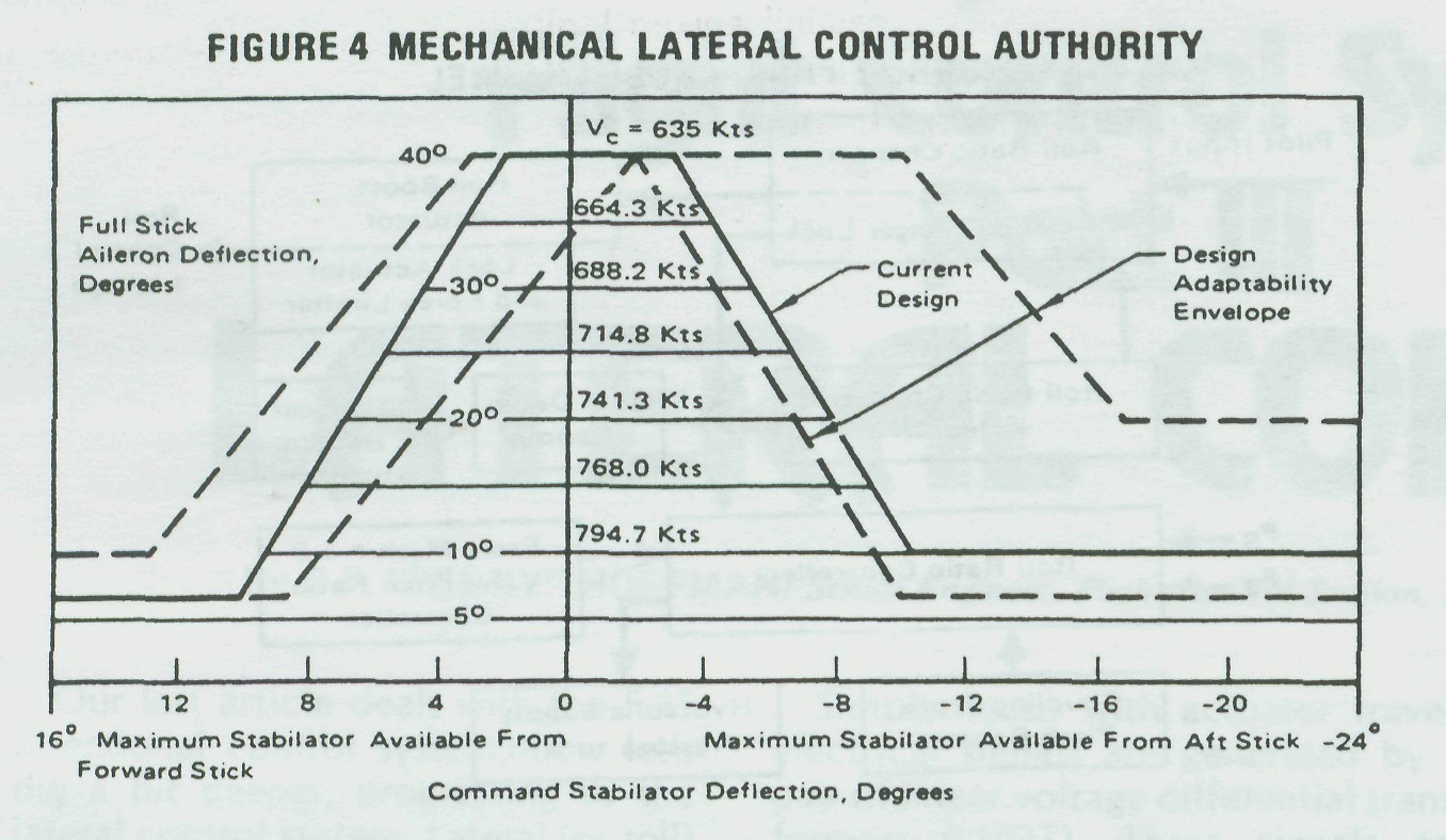
Fig. #4: Mechanical Lateral Control Authority
The only situation in which the ratio controller cannot command the ratio changer actuator to move is when the landing gear handle is positioned to extend the gear. During the early days of F-15 flying,it became apparent that during crosswind landings more than the available roll power was needed to keep the upwind wing from rising. As previously stated (and shown in Figure 4), when the aircraft is slowed to land and the stick is either trimmed or held aft, roll power is "washed out" (the amount of aileron available with full stick is reduced). The problem was re-solved by adding a solenoid valve to the ratio changer actuator which drives the ratio changer actuator to maximum ratio when the landing gear handle is placed in the down position. All production PRCA's have this feature so it is not possible to check aileron/differential stabilator washout on the ground without putting the gear handle up (with hydraulic pressure applied, this just "ain't" a good idea).
A suitable ground check may be made by pulling the PRAD CONT (Pitch and Roll Adjust Device Control) circuit breaker. This circuit breaker removes dc power from the gear down solenoid and aileron washout may then be checked. With the stick at takeoff trim, apply full left roll deflection and note the position of the ailerons.

While holding full left stick, slowly pull the stick aft, noting that the ailerons will begin to return to streamline stopping at about a 3 to 5 degree deflection as the longitudinal stick reaches the 3/4aft travel point. Returning the stick to neutral in pitch causes the aileron deflection to increase again to maximum. The same conditions may be seen for a right stick and for either forward or aft pitch inputs. Resetting the PRAD CONT circuit breaker removes the aileron washout function.Another signal to the roll ratio controller is a hydraulic input from the pitch ratio controller "Mach = 1.0" sensor. The roll ratio controller contains a hydraulic shutoff valve which controls the hydraulic supply pressure to the ARI. This is the switching intelligence for turning off the mechanical ARI above Mach 1.0.

Roll Booster � The last major component in the PRCA roll channel is the roll boost actuator. The booster control valve is coupled directly to the output of the ratio changer and the valve directs hydraulic pressure to a conventional power cylinder to drive all the downstream linkages external to the PRCA.

The boost actuator has two purposes. First, it prevents any of the downstream linkage friction from being felt at the control stick. Second, the actuator output force is sufficient to provide chip and foreign object shearing forces. In event of a hydraulic failure, or if the pilot selects emergency operation, the boost actuator control valve input arm locks at neutral. Both sides of the boost piston are ported to return pressure, and the actuator functions as a fixed link. Pilot inputs must then physically move the actuator piston as well as all the downstream linkage. This is why the stick forces become a bit higher during emergency operation.

MECHANIZING THE PRCA        ROLL OUTPUTS
The output shaft of the roll booster actuator carries the modified lateral commands of the control stick through a conventional system of push rods and bellcranks to the next major component, the lateral/longitudinal mixing linkage.

Mixing Linkage � The mixing linkage receives both lateral and longitudinal control stick inputs, decides which control surface is supposed to move, and pulls or pushes the appropriate control rod to deflect the surface. Figure 5 shows an expanded layout of the mixer which fits together in the shape of a parallelogram. Referring to the expanded view, a lateral input deflects link 1 pushing one aileron rod while pulling the other. At the same time link 2, connected to link 1 by link 4, rotates, deflecting the stabilators differentially. A longitudinal stick input to link 3 rotates it, pulling link 2 which pulls or pushes both Stabilator rods, giving collective Stabilator.


Fig. #5: Lateral/Longitudinal Mixing Linkage
A long, detailed explanation should not be necessary if you keep in mind that during lateral inputs all links move as a unit, rotating about the pivot. During longitudinal inputs, link 1 remains fixed and link 2 moves back and forth rotating about links 3 and 4. Two Linkage Paths � From the mixing linkage there are again two linkage paths.

� The aileron path utilizes push rod linkage to the lateral safety spring cartridge. The safety spring cartridge is connected in series with the lateral control linkage and allows the other aileron (plus differential stabilators) to continue functioning even though the linkage in one wing is hopelessly jammed. The safety spring cartridge is attached to a system of bellcranks and cables, carrying the lateral command to the wing root area. Push rods and idler bellcranks then carry the command to the aileron power cylinder control valve which ports hydraulic pressure to a single system actuator, deflecting the control surface.

The aileron power cylinder is a bit different than those used on previous McDonnell-built aircraft. The actuator body is fixed to the airframe and the linear operating ram is attached to the control surface. A mechanical feedback arm is connected between the ram and control valve to stop actuator travel when the input command is satisfied. In the event of total hydraulic loss to either actuator (Power Control is primary and the switching valve does not switch in Utility backup), the actuator contains internal valving which enables it to revert to an aileron damper.

� The differential stabilator path is quite similar to the aileron path, again utilizing a bellcrank/steel cable arrangement to carry the command to the aft torque tubes in each tail boom. The aft torque tube motion displaces each stabilator actuator control valve the prescribed amount and direction to cause differential deflections of the stabilator control surface.

The stabilator actuators, though more complex, are similar in design to the aileron power cylinders and are dual systems, containing CAS actuators. The stabilator power cylinders will be discussed in considerably more detail in the next article in this series, which will focus on the longitudinal control system.

 楼主| 发表于 2014-5-5 15:03:05 | 显示全部楼层
F-15 Flight Control System
Part IV - Longitudinal Control
By B. P. "PERRY" HOFFMAN/Senior Engineer, Flight Control Section, Avionics Engineering Laboratories
In the preceding article of this series, we discussed how the Pitch Roll Channel Assembly (PRCA) roll channel adjusts the ratios or gearing between the pilot's control stick and the ailerons. The pitch portion of the PRCA is in many ways identical, but is somewhat more complex. This complexity comes through use of a PRCA device called the Pitch Trim Controller (PTC), which automatically adjusts the longitudinal trim to maintain a constant pilot-selected load factor. We'll cover the PTC in some detail later, but meanwhile let's take a general look at the Longitudinal Control System (Figure 1).

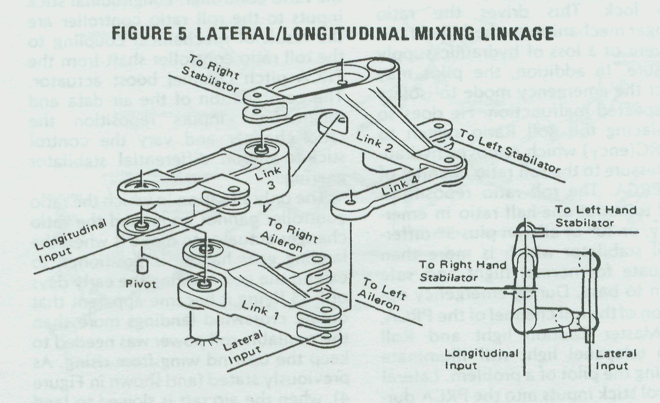
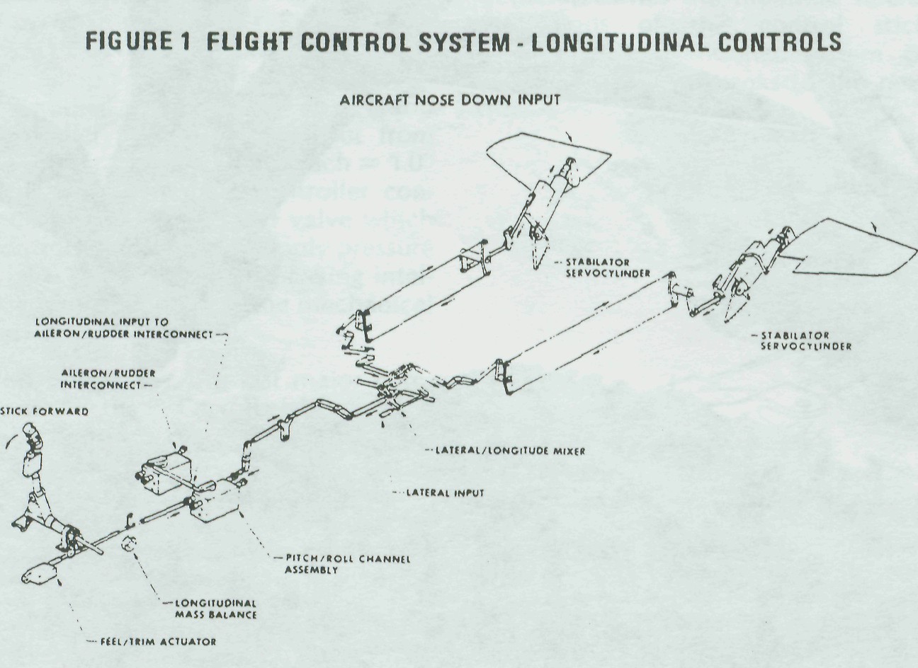
Fig. #1: Flight Control System - Longitudinal Controls
PITCH FEEL TRIM ACTUATOR
Beginning at the extreme left of the diagram, the first major component affecting control stick operation is the pitch feel trim actuator. It is designed to be in parallel with the total longitudinal linkage.

The zero-force or hands-off stick position is varied when the pilot presses the pitch trim switch on his stick. The pitch trim actuator moves the trim position of the control stick and linkage to satisfy pilot requirements. The only force the pilot normally feels when he moves the stick is generated by a dual-spring cartridge which is part of this trim actuator. These dual springs give the stick a higher force per inch displacement near the trim position and a reduced force per inch for larger stick inputs. This reduces the force a pilot has to hold for sustained high g maneuvers.

Electrical commands from the control stick trim switch or the takeoff trim button extend or retract the trim actuator. Linear Voltage Differential Transformers (LVDT) are mounted on the actuator and generate electrical signals which advise the CAS computer of the new trim position so that the CAS will not try to defeat the pilot-desired trim change. These same signals are also used by preset level detectors which shut the trim actuator off before the actuator reaches its mechanical limits.

When the takeoff trim button is depressed, the trim actuator drives to a pre-determined position dictated by preset detectors within the CAS computer. The electrical sensors and components associated with the trim system are dual so that a loss of any one element causes the trim to shut down, preventing a runaway trim condition for a single failure.
Moving aft from the trim actuator, there is a lead weight on an idler arm. This is not a "bobweight" for generating stick force per g, as is the case in the F-4, but is there simply to balance the control system so that sudden acceleration or deceleration of the aircraft does not produce stick motion.

PRCA
To begin with, let's break the PRCA pitch channel into its components (Figure 2) and see how each affects the longitudinal controls. The input rod offers two linkage paths with the main path tying directly into the ratio changer linkage, and a second input being supplied to the Load Factor Sensor portion of the Pitch Trim Controller.

Pitch Ratio Changer -- The pitch ratio changer utilizes dual redundant parallelogram linkage identical in operation to the roll ratio changer described in our last DIGEST article on lateral controls. The only operational difference is that the pitch ratio changer gearing utilizes a 6:1 ratio, where the roll ratio changer utilizes a 4:1 ratio.

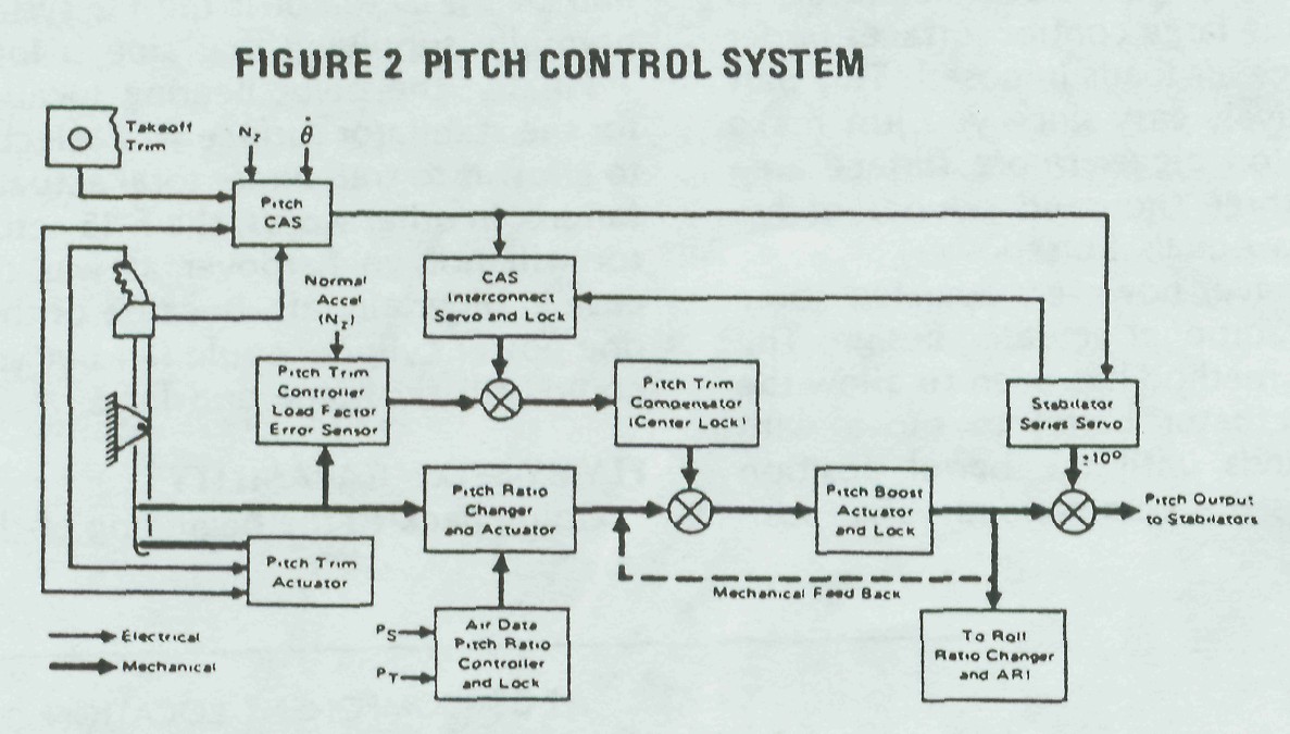
Fig. #2: Pitch Control System
Pitot (Pt) and static (Ps) information is supplied from the left-hand probe to the ratio controller bellows assembly, repositioning a cam-operated valve supplying hydraulic pressure to the ratio changer actuator. The ratio changer actuator then drives the changer linkage, varying the stick-to-stabilator gearing as required.

If hydraulics are lost to the PRCA, or if the pilot selects the EMERC position of the pitch ratio changer by actuation of the Pitch Ratio switch, the pitch ratio changer will drive to its failed position. In the failed mode, the gearing ratio is one-half of its maximum value and all other functions (PTC and Boost) are inoperative.

Two additional functions are associated with the ratio changer (one is no longer used, but a note of explanation is in order in case you see it on a schematic diagram). Early in the program there was a gear down valve which drove the pitch ratio changer to maximum (for landing control) when the nose gear proximity switch actuated. The disadvantages seemed to outweigh the advantages, so the valve has been deactivated on current Eagles and the valve will not be in future PRCA's. For the maintenance man, this is a great help since he can simply place the Pitch Ratio switch to emergency and check the fail mode without having to simulate a gear up condition.

The second function is a safety feature controlled by the pitch ratio changer actuator. If a hardover failure of the pitch trim controller occurs at low pitch ratios, the pitch CAS is inoperative, longitudinal control could be lost. To guard against this possibility, a valve within the ratio changer actuator is opened when the actuator approaches the minimum ratio position. This valve supplies hydraulic pressure to an interlock piston within the pitch trim compensator, keeping it at a position where adequate control is always available.

The output of the pitch ratio changer is fed to the pitch boost actuator servo valve. The boost actuator output is mechanically linked back to the servo valve input, closing the loop. The boost actuator output also feeds the downstream linkage, which deflects the stabilators and drives the linkage scheduling the roll ratio controller and the ARI. As you will recall from our previous articles, the pitch output is used in roll to schedule the roll ratio as a function of angle of attack. Yaw is affected by this also, since yaw gain increases as roll gain decreases. No more rudder rolls, guys; all you need for high angle of attack maneuvering is a lateral input from the stick.
The pitch trim compensator is mechanically coupled to the pitch boost actuator control valve. The motion of this device adds (or sub-tracts) boost actuator displacement (pitch output to stabilators) to what the ratio changer output position is commanding. The action of the pitch trim compensator is controlled by the pitch trim controller.

Pitch Trim Controller �
The pitch trim controller adds or subtracts stabilator deflection to compensate for such aircraft variables as increases or decreases in airspeed, speed brake/flap extensions, or changes in loading. These changes are introduced without movement of the control stick. These combined PTC and pitch ratio changer outputs result in a nearly constant stick force and stick position per g within the Eagle's operating envelope (about four pounds of stick force results in one-half inch of stick displacement, producing a load factor of one g). The name given this feature is "series trim." The concept is not new; it's been tried on several previously-built aircraft. The uniqueness of this feature in the F-15 lies in the fact that it works, and does so without electrical inputs.

Stick inputs are fed into a high-class, accelerometer-controlled servo loop known as the load factor error sensor (LOFES), a part of the PTC. This stick input establishes the neutral or zero point it works around. For example, let us assume that a pilot, or the trim actuator, is holding the stick in a position commanding a load factor of one g. Any subsequent deviation from that setting will be sensed by the PTC accelerometer which will valve hydraulic pressure to the pitch trim compensator piston, repositioning the piston and commanding the required amount of collective stabilator to keep the aircraft at one g. This series trimming capability is true for disturbances created by flap, speedbrake, and landing gear extensions. Acceleration and deceleration are also compensated for, producing an essentially neutral speed stable airframe. Since the trim change we've described is "series," no stick movement is noted.

A rapid warm-up valve has recently been added to the PTC. Hydrome-chanical devices such as the PTC utilize extremely close tolerances in their construction and don't want to work well when the surrounding metal and hydraulic oil are cold. Because of this, a viscosity sensing bridge coupled to the PTC pressure inlet bypasses the input hydraulic oil through a small orifice which speeds the warm-up process and allows normal control operation sooner. All production PRCA's contain the warm-up fix, as do most flight test units.

LINKAGE
Control rods carry the PRCA output to the mixer linkage. The mixer linkage combines the pitch command with the roll system signals to drive the stabilator (a diagram of the mixer linkage was presented in the article about roll control in the last issue). Then a system of dual cables and bell-cranks extends along the major length of the fuselage to the aft torque tube. The aft torque tube carries the pitch commands directly to both stabilator control valves, causing actuator displacement and resultant stabilator deflection.
  
These cables may be a prime contributor to flight squawks such as"too much stick motion with no aircraft re-sponse," or "soggy longitudinal controls." Maintenance personnel should pay special attention to cable tensions. If readjustments are necessary, be sure that they are made to both cables to keep the end bellcranks parallel (the rigging pin can be installed in both ends). Refer to Technical Order 1F-15A-2-5 for the final word.

STABILATOR POWER CYLINDER
The final components of the pitch channel are the two stabilator power cylinders and if they don't work, it's a long walk home. A lot of thought went into the Eagle actuators; they obviously had to have considerable muscle to move the large control surfaces under the large air loads imposed. This part is relatively easy since you just make the piston bigger (more surface area times three thousand pounds of hydraulics equals horsepower).

We have, however, deviated some from traditional actuator design. The normal method has been to allow the total actuator barrel to move with commands until the barrel position matches the commanded valve position, stopping actuator motion. In the F-15, the actuator is firmly attached to the airframe and the ram is attached to the stabilator. A mechanical feedback linkage is then employed to shut off the input valve when the actuator has reached a new position. This method is deemed best from a structural standpoint and decreases the total mass which must move.

The actuator contains two identical pistons powered by separate hydraulic systems. Either of these systems can adequately control the stabilators. In the event of two hydraulic system failures, one-half the actuator remains functional with get-home-safe capability because the Utility hydraulic system automatically switches into one-half of the actuator if the PC system normally supplying that side is lost.

Finally, the pivot bearing location for the stabilator surface was selected to allow it to trail under total actuator failure. In other words, the F-15 actuator will not go hardover as was the case in older aircraft. Because of this, one power cylinder could fail but you could still fly home and land.

FLY-BY-WIRE CAPABILITY
Going back to the beginning of the pitch system, the pitch trim actuator is physically located as close as possible to the control stick.
  
This permits the pilot to "fly by wire" with normal stick feel, using the CAS stick force sensor should the mechanical linkage be-tween the stick and stabilator actuators break or disconnect.

Snicker if you must, but an early Eagle was flown back to the nest and landed safely with a total mechanical disconnect of the longitudinal controls. Control stick feel to the pilot was normal despite a control rod having been completely severed by an ECS turbine blade.

To allow this fly-by-wire capability, a centering, or detent, spring was added to the input valve area. If a linkage disconnect occurs ahead of the power cylinder, the valve centers itself. At this point, the CAS commands the actuator travel within its authority of plus or minus ten degrees of stabilator travel, enough to get home safely. Jammed linkage poses a different problem since the CAS must work around the jammed valve position, but even this is not impossible.

Our next article will pick up where we've left off here; we'll look into the overall CAS functions in the F-15.


Fig. #3: AFCS Component Location (F-15)

 楼主| 发表于 2014-5-5 15:03:51 | 显示全部楼层
F-15 Flight Control System
Part V - Yaw and Roll Control Augmentation
By B.P. "PERRY" HOFFMAN/ Senior Engineer. Flight Control Section, Avionics Engineering Laboratories
Having taken a look at the mechanical aspects of the F-15 Flight Control System, let's turn our attention to the electronic portion, the Control Augmentation System. Possibly the most frequently asked questions are: "Just what is the Control Augmentation System?" "What does it do for me?" "How does it do it?"

The Control Augmentation System (CAS) consists of two distinct functions. The first is our old friend, the Stability Augmentation System, otherwise known as Stab Aug or SAS. For those old-timers who can remember far enough back, this used to be called a Damper. The Stab-Aug, or Damper, portion of the F-15 CAS is designed to help stabilize the airframe, compensating for unwanted motion which might occur as a result of wind gusts or disturbances.

The second CAS function is its Control Stick Steering mode. This measures, compares, shapes, and smooths out pilot stick and pedal inputs allowing precise and comfortable control throughout the maneuvering envelope

Why is CAS desirable? Well, we know that the F-15 airframe is basically stable, and that the manual flight controls are designed to give Level II handling without augmentation. (Military Specification MIL-F-8785B de-fines Level II handling as "flying qualities adequate to accomplish the mission Flight Phase, but some increase in pilot workload or degradation in mission effectiveness, or both, exists.") Despite the basic stability of the Eagle, various flight conditions and varieties of store loadings could result in some pretty touchy handling situations were it not for the CAS. In addition, the CAS provides safe control of the aircraft should the basic mechanical system suffer failure or battle damage such as foreign object jams or shot-away linkage.

The bulk of this article will be concentrated upon the yaw and roll CAS (you'll see, shortly, that these two functions can't be separated). The pitch CAS will be the subject of a future article.


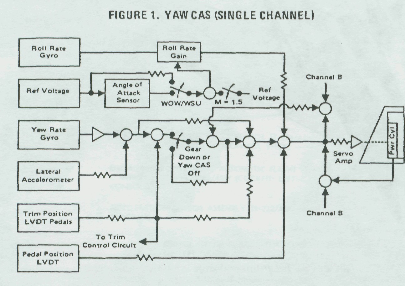
Fig. #1: Yaw CAS (Single Channel)
YAW CAS
Sideslip Control and Damper - Precise sideslip control is provided during maneuvering by the yaw CAS. Referring to the yaw channel block diagram (Figure 1), you'll see a Rudder Pedal Position Linear Voltage Differential Transformer (LVDT). As the pilot applies force to the pedals, the me-chanical system begins to deflect the rudders. At the same time, the pedal position LVDT generates an electrical signal. As the aircraft responds to the pedal input, the yaw rate gyro and the lateral accelerometer will sense this motion.
Their blended signals are compared to the pedal position LVDT signal within the Roll/Yaw Computer and the resultant signal output either adds or subtracts rudder control surface deflection as needed to obtain the proper response. Likewise, this combination of signals directs the servo amplifiers to deflect the rudder power cylinder and rudder control surfaces the correct amount and direction to dampen any unwanted yaw disturbance.


Elimination of Steady-State Sideslip - A circuit was added to reduce uncommanded and persistent sideslip (due primarily to rudder linkage friction or hysteresis) during supersonic flight and following a maneuver. The combined lateral acceleration and yaw rate sensor feedback voltages are compared with the rudder trim position and the combined output is used by the Proportional plus Integral (P + I) circuit to apply rudder surface deflection in a direction to eliminate the sideslip. With a maximum authority of �3.75 degrees rudder, pilots can expect the ball to be pretty well neutral during flight.

There is, however, one disadvantage to the P + I circuit. If rudder surface hangup exceeds the P + I authority, yaw CAS cannot automatically trim the aircraft to zero sideslip. Thus, some manual pedal trim may be required to make up the difference, reducing sideslip to minimum. Manual trim should be applied slowly, or in small amounts with waiting periods, since the new pedal LVDT position affects the integration of the P + I circuit. If this procedure is not followed, it may appear to the pilot that he is chasing the trim.

Pilots can expect to see yaw trim changes varying in magnitude with different aircraft anytime the landing gear is extended or yaw CAS is disengaged. Both of these actions drive the P + I integrator to zero, introducing a yaw transient. So we may have solved the supersonic sideslip problem but created a problem at yaw CAS shutdown.

Maintenance personnel will have to locate and reduce system friction to a minimum. A good source of system friction can be found in the flexible cables. Here are a few points to keep in mind:

� Any kinks or rough spots are
cause for cable replacement.

� At any attach point such as bellcranks or ARI output rods, attempt to line up the cable end exactly with its attach point. In other words, reduce any apparent side load; the nature of the ribbon cable is to increase friction loads as side force is exerted on the ends.

� Make changes in direction with as large a radius as possible with only minor twists.

To summarize, problems will go away when mechanical rudder linkage is kept friction-free.
Failure Detection and Shutdown -
All three CAS channels utilize a dual-channel "Fail-Off" system. There are several things that would cause the failure detection circuitry to shut down CAS: if spin is evident (yaw rate exceeds 41.5 degrees/second); a malfunction unbalances the yaw computation circuits; an imbalance between the rudder actuators; and failure of the rudder actuator shut-off valves. Let's amplify a bit on these situations -

� If CAS is causing or aggravating the spin mode, we want CAS off. Therefore, any yaw rate in excess of 41.5 degrees/second will cause yaw CAS to shut down. Roll shuts down as a result of yaw shutting down and pitch follows if the high yaw rate continues for a period of longer than 120 milliseconds.

� Yaw CAS will shut down for malfunctions which unbalance the yaw computation circuits. This may result from differences in one of the dual yaw rate gyros or lateral accelerometer output voltages which exceed a preset level. The system will also be shut down by an electronic failure within the yaw computation circuits.

� A shutdown of yaw CAS will occur if a problem in the system causes one rudder hydraulic actuator to mistrack the other by approximately four degrees for a period of one second or longer.

� The final cause for shutdowns        applies to production computers Part Number 275E514G3 which will be installed effective F-15 ship 61 and TF-15 ship 14. Circuitry has been added to these computers which senses open wiring to the rudder surface actuator shutoff valve or a failure of the actuator shutoff valve itself. In the older C2 computers, an open in shutoff valve wiring renders the yaw CAS inoperative; however, the roll CAS will not be shut down and the roll and yaw CAS telepanel lights remain out. Because of the inoperative shut-off valve, electrical signals from the CAS will not affect the rudders; the only rudder movement will come from mechanical inputs. Since the rudders will not mistrack in this mode, there will be no shutdown.

During preflights (maintenance and aircrew), ground personnel should double check to insure that yaw CAS inserts an additional 50 percent (or 15 degrees) of rudder surface deflection, making a total surface movement of 30 degrees (these figures are approximate).
Aileron Rudder Interconnect - In order to improve turn coordination, roll rate signals are applied to the yaw channel. Since greater rudder deflection is required for turn coordination at high angles of attack, this roll rate signal is scheduled with angle of attack, increasing rudder deflection as angle of attack is increased. To minimize roll and yaw coupling tendencies, ARI is defeated at Mach numbers above 1.5 and for negative angles of attack by driving the ARI signal to zero. The ARI signal is also driven to zero with wheel spin up. This is one of the aids for better control during crosswind landings. With ARI operational during a nose-high rollout, and with lateral stick held to lower the up-wind wing, ARI would add rudder in a direction to drive the nose into the wind.

Control Surface Actuators - The muscle for the Eagle's rudders is not the conventional linear ram-type actuator normally seen on aircraft flight control systems. To minimize space requirements, a rotary actuator was designed which is an integral part of the rudder hinge line. Not only does it receive manual inputs, but also electrical inputs from the servo amplifier. These signals control an internal piston which deflects the rudder control surface upon CAS command. The rudder actuator is also load-limited so that as inflight loads increase the actuator deflection is decreased accordingly, reducing unwanted tail loads. In the event of hydraulic pressure failure to either actuator, bypass valves prevent oil from escaping into the return line. In this condition, the rotary actuator becomes a self-contained surface damper.

Problem Areas - Yaw CAS (as well as CAS in general) has an excellent record of reliability. Once "infant mortality" rids the computers of problem components, the next malfunction is pretty far down the road. During production flights at St. Louis, we have replaced two rate gyro packages - one had a loose connection in an individual gyro, the other was out of tolerance gradient-wise. No accelerometer sensors have been replaced to date.

Some difficulty may be experienced when yaw CAS is initially turned on-the first pedal application may result in a yaw shutdown. The reason for this involves the locking rings which hold the rudder actuator CAS rams at zero while CAS is disengaged. During yaw CAS turn-on, these rings must move to unlock the CAS ram. Sometimes the unlock ring of one rudder actuator lags the ring in the other actuator. As rudder pedal force electrical signals attempt to move the rudders, one rudder CAS ram encounters the not-fully unlocked ring. This results in a slight lag in one of the rudders. If this lag exceeds four degrees, the failure detection circuits will be triggered. The corrective action, in this case, is to reset yaw CAS and you should be back in business with normal operation.

  Fig. #2: Roll CAS (Single Channel)
ROLL CAS
Roll CAS (Figure 2) provides stability augmentation (or roll damping) as well as supplying the maneuvering capabilities to satisfy Level I lateral control requirements throughout the F-15 envelope (Mil Spec MIL-F-8785B defines Level I as "Flying qualities clearly adequate for the mission Flight Phase.) Short period roll oscillations and aerodynamic disturbances are sensed by dual roll rate gyros whose outputs are shaped and amplified and sent to the stabilator actuators, not to the ailerons as one would expect (there are no electrical inputs of any kind to the Eagle's ailerons). The stabilator control surfaces operate differentially to stop the unwanted roll disturbance and restore stable flight.

Electrical commands from lateral force inputs to the pilot's control stick force transducrr (located both forward and aft in the TF-15A) are first applied to a deadband circuit in order to desensitize the roll commands around the neutral point. The roll command is then switched as a function of Mach number. In this process, the larger gradient assures that the time-to-bank requirements are available at the lower speeds. The lower gradient reduces the roll/yaw coupling tendencies at Mach numbers in excess of 1.5.

Dual roll rate gyros measure aircraft response to a lateral control stick input. The roll channel of the roll/yaw computer then adds or subtracts differential stabilator deflections to assure the proper response. Roll CAS authority is a maximum of �5 degrees differential stabilator relative to the position selected by the mechanical control system.

The roll CAS error is limited by functions of airspeed and angle of attack. The airspeed limit is employed so that excessive structural loads are not generated on the differential tail. The scheduling signal is derived by the Dynamic Pressure Sensor Unit of the Automatic Flight Control Set. This unit receives pitot and static pressures which drive dual potentiometers. The output is then shaped to provide the proper gain schedule as shown in Figure 3. The gain potentiometer excitation voltages are switched through a lag network upon roll CAS engagement to reduce transients.

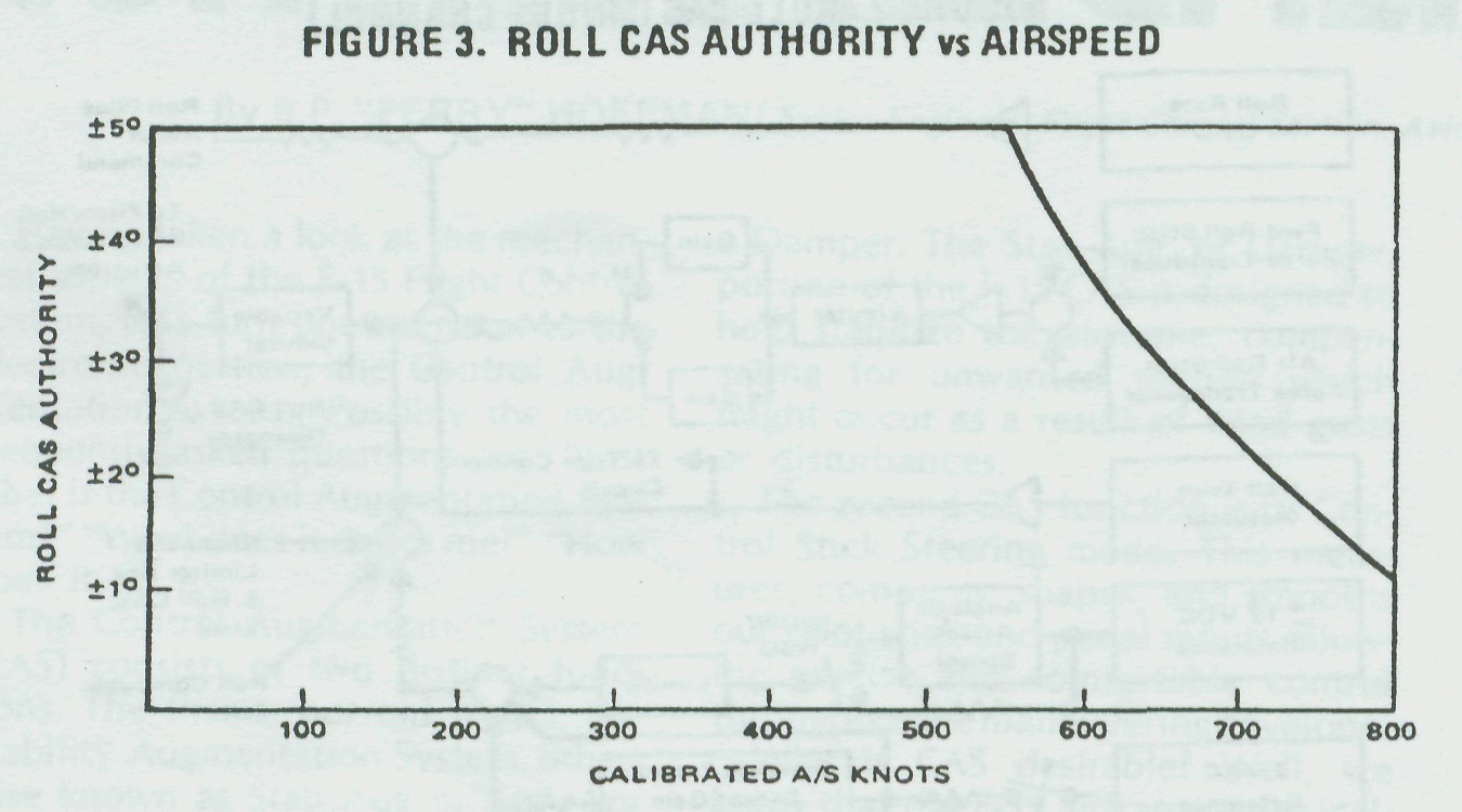
Fig. #3: Roll CAS Authority vs Airspeed
Additional roll CAS limiting is required to reduce the roll/yaw coupling for negative angles of attack, and at large positive angles, to minimize the adverse yaw. This provides an equivalent to the "aileron washout" function of the mechanical control system which was discussed in an earlier article. The angle-of-attack limiting is subtracted from the airspeed schedule as indicated in Figure 4.

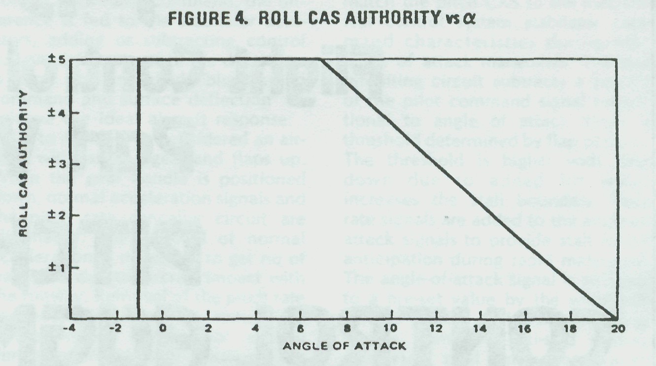
Fig. #3: Roll CAS Authority vs α
No roll CAS is desired at angles of attack above 20 degrees. This prevents the adding of pro-spin controls through uncommanded pilot-induced CAS inputs, and roll damper inputs, at the higher angles of attack. The angle-of-attack schedule is switched to a fixed reference at wheel spinup to assure that full roll CAS authority is available for adequate crosswind control during landing rollout.

Failure Detection - As in the yaw CAS, there are a number of ways in which the system can detect and react to system abnormalities -

� Like the yaw channel, the Roll CAS sensors must track each other by preset limits. When these limits have been exceeded by any sensor, or if a failure occurs in the roll CAS computation electronics, roll CAS shuts down.

� Roll CAS also shuts down, and remains down, if yaw CAS fails or is turned off by the pilot. This assures that no adverse roll/yaw coupling will occur.

� Since roll and pitch CAS share the stabilator servo actuators, roll CAS will shut down if the pitch CAS fails. However, if there has been no failure of the roll computation, and if the stabilator servo actuators are still operative, the roll CAS can be reset and will operate normally. This is a pretty good troubleshooting aid. If a failure of pitch and roll CAS occurs, but roll can be reset, it is unlikely that the stabilator actuators, or the wiring to the actuators, are at fault. In this case, check the pitch CAS computation circuitry and the sensors.

� The primary means of detecting failures within the roll and pitch CAS servo loops consists of monitoring the level of error of a differential pressure sensor (DPS) hydraulic ram (one in each stabilator actuator). As long as the servo signals are equal, the DPS error is zero and the system will operate normally. Failure of a servo valve, or electrical failure of an actuator LVDT, will drive one or the other DPS ram hardover. As a result, roll and pitch CAS will shut down. A lag network is employed to filter the DPS error signal being monitored, minimizing nuisance shutdown. With the DPS failure detection scheme just described, a fast-operating, high-authority CAS can be employed with an acceptable level of failure transients for hardover servo valves, or in the event an actuator LVDT output is lost.

This presentation of the F-15 Control Augmentation System will be continued in our next issue of the DIGEST as we take a look at the pitch CAS.


 楼主| 发表于 2014-5-5 15:04:22 | 显示全部楼层
F-15 Flight Control System
Part VI
Pitch Control Augmentation
By B. P. "PERRY" HOFFMAN/Senior Engineer, Flight Control Section, Avionics Engineering Laboratories
To conclude this series of articles about the F-15 Flight Control System, let's look at the Pitch portion of the Control Augmentation System (CAS) and the Attitude/Altitude Hold modes. Please stay with me to the end; while I've attempted to remove most of the mysteries surrounding this complex electronic system, it hasn't been easy and I hope we all don't get too confused.

Pitch CAS/Single Channel - The operation of the pitch channel electronics is similar to yaw and roll in that Pitch CAS performs two functions. First, conventional stability augmentation improves ride comfort by reducing or eliminating undesirable aircraft motions from disturbances such as wind gusts. The second operation provides the pilot with precise control of aircraft performance by measuring the aircraft response to a given command, and adding or subtracting stabilator deflection as required to match the command to the "ideal."

Stability Augmentation - As shown in Figure 1, the prime sensor used for damping the unwanted pitch oscillations is the pitch rate gyro. When the aircraft receives a change in its flight path, the resultant rate of change is sensed by the rate gyro. A corrective signal is generated by the pitch rate sensor and is fed to a buffer demodulator, then a rate canceller (which eliminates steady signals), and to a variable limiter (which eliminates switching transients during landing


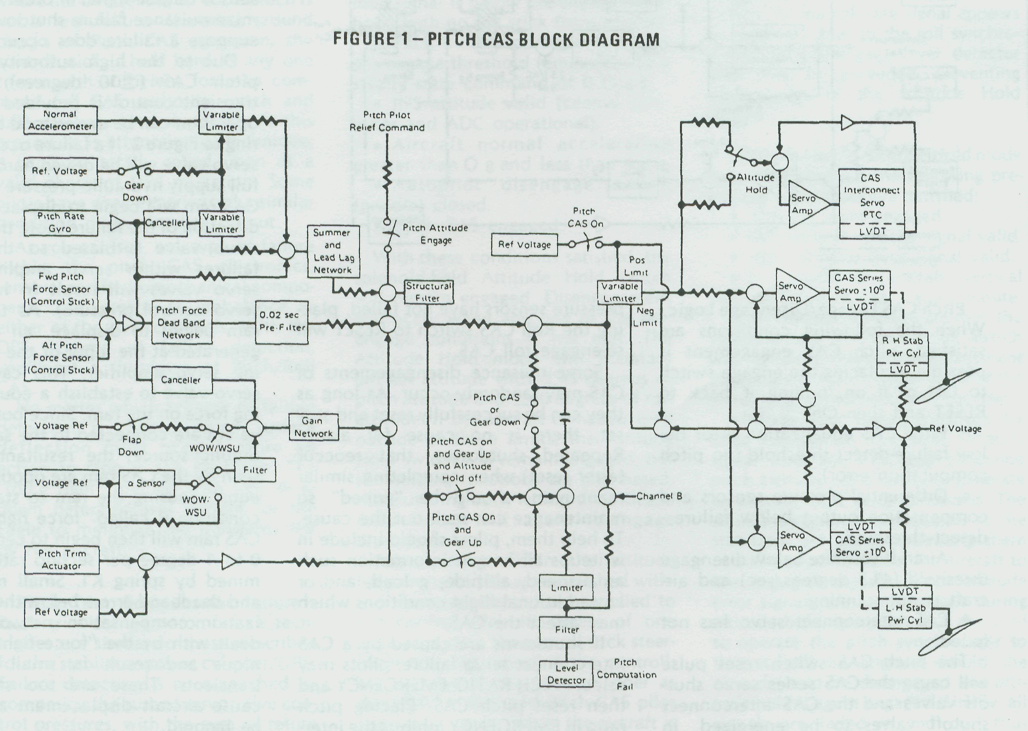
Fig. #1: Pitch CAS Block Diagram
gear operations). The rate signal is then summed, shaped, and sent to a structural filter which reduces frequencies that would cause coupling to the airframe, producing unwanted stabilator oscillation.

The variable limiter performs two functions. When the Pitch CAS switch is reset, the limiter slowly increases CAS authority from zero to 10 degrees. Secondly, it forces the roll and pitch channels to share the 10 degree authority over the stabilator actuators by limiting the amount of CAS series servo deflections either channel can command when the mechanical pitch deflection is greater than 18 degrees nose up.

The modified corrective rate signal is then applied to a servo amplifier which electrically commands the servo valve to extend or retract the 10 degree CAS series servo (internal to the stabilator power cylinder), repositioning the main power cylinder control valve, and porting hydraulic pressure to the power cylinder main ram piston. When the main ram piston deflects, it repositions the stabilator control surface in a direction to stop the unwanted airframe disturbance. An electrical follow-up signal is generated by the 10 degree CAS series servo Linear Voltage Differential Transformer (LVDT) which opposes the corrective rate signal input. When sufficient series servo deflection is obtained to match the rate signal input, series servo deflection stops. The aircraft rate of change in its flight path will grow smaller, and the follow-up LVDT signal starts to return the series servo to neutral. When the aircraft flight path is again stabilized, the rate signal is zero and the CAS series servo is at neutral.

A condition where no aircraft rates are being generated and corrective action is being taken by pitch stab aug is pretty hard to come by. The pitch stab aug is constantly working to maintain a stable airframe. (For the sake of simplicity, we only considered a single channel rate disturbance.)

Pitch Control Augmentation - Looking again at Figure 1, find the forward and aft pitch force sensors (F-15A or TF-15A). Longitudinal stick force commands from one (or both) control stick force transducers are summed together and fed through a deadband/ dual-gradient circuit (prevents over-sensitivity near null and reduces stick forces during sustained high "g" maneuvers). The resultant stick force command then goes through a 0.2 second pre-filter for smoother system responses to sharp pilot inputs (this improves tracking characteristics). The shaped command signal is then sent through the same structural filter as the stab aug rate signal, and on to the variable limiter. The variable limiter, used for stab aug and pilot commands, has the same reason for being in the circuit and operates the same as was explained in the stab aug section.

The pilot command is then sent equally to the left and right servo amplifiers which electrically command the servo valve to extend or retract the 10 degree CAS series servo, repositioning the main power cylinder control valve, and porting hydraulic pressure to the power cylinder main ram piston. Deflection of the piston repositions the stabilator control surface in the direction desired. Two LVDT follow-up signals are generated by the movement of the stabilator power cylinder. The main ram LVDT signal provides the intelligence for the variable limiter, telling the limiter just where the stabilator control surface is located. The other follow-up signal is again the CAS series servo position and stops series servo displacement when the input signal level is matched. Aircraft response to a pilot's stick force command is measured by the pitch rate gyro and normal accel-erometer sensor outputs. These signals meet at the summing/lead lag network. If the measured response after summation does not agree with the control stick force command, the difference is fed to the stabilator actuators, adding or subtracting control surface deflection until the difference is zero. This is called "blending of command and surface deflection" to achieve the ideal aircraft response.

Up to now, we've considered an aircraft with landing gear and flaps up. When the gear handle is positioned down, normal acceleration signals and the pitch rate canceller circuit are eliminated. The removal of normal acceleration is necessary to get rid of transients due to aircraft impact with the runway. Removal of the pitch rate canceller circuit at the same time insures stable longitudinal control during approach and landing. The reduction of these two signal levels is achieved through variable limiters which have a one-second time constant for fade in or out.

Angle-of-attack signals are also used by the pitch CAS to inhibit stalls andmatch the pitch CAS to the mechanical control system stabilator command characteristics during high angle of attack maneuvers.
The stall inhibiting circuit subtracts a portion of the pilot command signal proportional to angle of attack above a threshold determined by flap position. The threshold is higher with flaps down due to added lift which increases the stall boundary. Pitch rate signals are added to the angle-of-attack signals to provide stall inhibit anticipation during rapid maneuvers. The angle-of-attack signal is switched to a pre-set value by the weight-on-wheels switch, or by wheel spin-up signals from the anti-skid sensors, removing stall inhibition during ground operation.

Pitch trim signals are also fed into the pitch CAS to tell the system what trim value the pilot requires. If this trim signal were not present, any manual retrim selected by the pilot would be defeated by the CAS returning the aircraft to the original trim position. Pitch CAS commands are also used to deflect the CAS inter-connect servo, located in the Pitch Trim Compensator module of the PRCA. These commands serve two functions. First, they insure that the mechanical and the CAS systems are tracking each other, minimizing any disagreement that may exist if the pitch CAS disengages and the mechanical system takes over. The second feature allows the CAS interconnect servo to carry an offset from null, allowing the CAS series servo (within the stabilator power cylinder) to maintain its full �10 degree authority.

Pitch CAS Engage/Disengage Logic -
When the following conditions are satisfied, pitch CAS engagement is possible by placing the engage switch to ON or if on, pulling it back to RESET and then ON.

� Pitch CAS equalization error below failure-detect threshold (no pitch computation error).

� Differential pressure sensors and compensation output below failure -detect threshold.

� Aircraft yaw rate below disengage threshold (41.5 degrees/sec) and aircraft is not spinning.

� CAS interconnect servo has not failed.

The pitch CAS switch reset pulse will cause the CAS series servo shut-off valves and the CAS interconnect shutoff valves to be energized. In addition, the differential pressure sensor failure - detect circuit and equalization integrator will be activated.

Activation of the series servo and interconnect servo shutoff valves latches the necessary logic to keep the shutoff valves engaged. Simultane-ously, another latch circuit activates the pitch CAS engage limiter, fading from 0 to 100% authority (� 10 degree series servo), extinguishing the tele-panel fail light.

Disengagement of pitch/roll CAS occurs if any of the pre-engage conditions indicate a failure. Roll CAS may be reset if the failure has not occurred within the stabilator power cylinder or power cylinder wiring.

As long as the CAS series servos and differential pressure sensors have not failed, placing the Roll CAS switch to RESET will re-engage roll CAS.

Some nuisance disengagements of CAS may randomly occur. As long as they can be successfully reset and stay set, there is no cause for alarm.
Repeated shutdowns, that reoccur (after reset) when completing similar maneuvers, should be "griped" so maintenance can seek out the cause. To help them, pilots should include in writeups all known information such as airspeed, altitude, g load, and/or any additional flight conditions which may affect the CAS.

If shutdowns are caused by a CAS interconnect servo failure, pilots may select PITCH RATIO EMERGENCY and then reset pitch CAS. Placing pitch ratio in EMERGENCY inhibits the interconnect failure detect logic. Pilots then have the option of flying at about one-half mechanical pitch ratio without hydraulic boost from the PRCA (this means you'll have higher stick forces). Also, mechanical ARI will be inoperative. With pitch ratio EMERGENCY selected, and an operational pitch CAS, sufficient longitudinal control is available for most maneuvers including adversities during the landing phase. Whatever method you select, leave pitch CAS shut down with full mechanical ratio (plus operational series trim from the pitch trim controller), or select emergency pitch ratio and reset pitch CAS. Slow down to a reasonable "q" before experimenting.

Failure Detection - The primary means of failure detection for Pitch CAS is the monitoring of voltage levels generated by a differential pressure sensor located in each stabilator power cylinder. Normally the voltage level will be zero (no failures) which satisfies an equalization integrator circuit of the CAS and shutdown will not occur. A lag network is employed to filter the differential pressure sensor output signal in order to minimize nuisance failure shutdowns. But suppose a failure does occur?

Fig. #2: Pitch/Roll Servoloop

Due to the high authority of the pitch CAS (�10 degrees), failure transient control is provided and its operation can be understood by referring to Figure 2. If a failure occurs, one servo valve will be driven hardover by full supply hydraulic pressure and the CAS ram will begin to displace in the direction of the failure (note that each servo valve is biased so that null failures within servo amplifiers or servo valves will result in hardover servo control pressure). As the CAS ram begins to displace, an error is generated at the input of the remaining servo amplifier. This causes its servo valve to establish a counteracting force on the ram. Since both servo valves are connected to the same hydraulic source, the resultant forces seen by the CAS ram are opposite and equal, causing the ram to stall. This condition is called "force fight." The CAS ram will then begin to center at a 0 to 1 degree per second rate determined by spring K1. Small mistrack and deadband errors below the equalization compensation networks are dealt with by the "force fight" technique and result in small engage transients. These are too small to cause aircraft displacement and can be ignored.
Looking again at Figure 2, note the        differential pressure sensor (DPS) ram and its associated connections. With no failures, pressure C1 and C2 on the right hand side of the DPS ram are equal and balance the combined pressures of Ps + Pr and spring K2 on the left side of the DPS ram. In this condition, equilibrium exists (no motion of ram) and the equalization compensation integrator output is zero (CAS remains set, no failures).

If pitch CAS component failure occurs, such as described in the "force fight" explanation, the equilibrium of pressures C1 = C2 on the right side of the DPS ram are upset and the DPS ram begins to drive slowly hardover. The DPS, LVDT signal is fed to the equalization compensation integrator which starts to slew in a direction to reduce the LVDT signal to zero. If the integrator signal has not reached zero in three seconds, a shutdown pulse is generated by the CAS and both stabilator �10 degree series servo shutoff valves are deenergized. Controlled orifices and spring-controlled locks center the CAS and DPS rams.

There is one normal condition where the DPS senses an error which is not a real failure. If during ground checks of Pitch CAS operation, the control stick is held hard in any one corner with sufficient force to command full CAS authority (pitch and roll), you may get a shutdown. As this procedure is a function of technique, it can't be totally relied upon as a valid check of DPS operation. Some pilots have even experienced a similar condition during landing rollout.

As you can see, any type of failure within the pitch CAS electronics, sensors, and hydromechanical components can create an imbalance in either of the dual channels. With the DPS scheme of failure detection, you'll get a shutdown of Pitch/Roll CAS.

No matter which scheme of failure detection is chosen, some surface deflection must occur before an action to stop it can be taken. The "force fight" method with DPS shutdown detection was chosen for the Eagle to minimize the transients felt by the aircraft.

Pitch Trim Compensator Failure -
Pitch trim compensator failure techniques are similar to those described for the stabilator power cylinder/DPS. Failure detection is accomplished by comparing the sum of servo valve control pressures, with the sum of return and regulated hydraulic supply pressures. A spring-loaded differential pressure spool is employed to compare the pressure, and if the hydraulic pressures are sufficient to overcome the detent spring loads (component failure of PTC interconnect servo), the ram deflects and opens redundant failure-detection switches. Opening of any of the PTC switches creates a failure pulse which shuts down the pitch CAS Pilot action with a PTC failure was discussed earlier.

Equalization of PTC failure detection is unnecessary since dual channel pitch CAS commands are averaged at the servo amplifier. This assures the same command to each channel and the PTC servo gains are considerably lowered. As a result, channel mistrack displacements are higher, but since the servo drives the PTC at a slow rate, the resultant transients are acceptable.

Roll/Pitch Pilot Relief Modes (Attitude Hold) - Attitude Hold modes may be engaged if all the following pre-engage conditions are satisfied:

� Roll attitude interlocks are present (yaw/roll CAS engaged and roll outer loop signal is below pre-engage threshold) with no roll stick force applied.

� Pitch outer loop signal is below pre-engage threshold (equivalent to a steady state command of 0.25 g.)

� INS attitude valid (central computer and ADC operational).

� Aircraft normal acceleration greater than O g and less than +4 g.

� Autopilot disengage switch        (paddle) closed.

� Pitch CAS engaged.

With these conditions satisfied, the solenoid-held Attitude Hold switch will remain engaged. Disengagement will occur when any one of the pre-engage conditions is not met. The Attitude Hold mode will maintain aircraft attitude with �45 degrees of pitch attitude and �60 degrees of roll attitude. If the aircraft is maneuvered outside of these limits, the Attitude Hold switch will remain engaged, but the holding functions are eliminated. Maneuvering back within the attitude hold limits will again re-engage attitude hold.

Maneuvering within the attitude hold limits can be accomplished without disengagement. Force applied to the control stick in excess of one pound actuates the control stick steering mode, repositioning the controlling surfaces in the same manner as described in Roll and Pitch CAS pilot command inputs. While the aircraft is maneuvering, the Pitch and Roll Attitude Synchronizer is unlocked and allows synchronization to the new attitude commanded by the pilot. When sticks force is reduced below one pound, Attitude Hold modes re-engage.

Both the Roll and Pitch Attitude Hold modes have solid state synchronizers. These follow the attitude information from the INS platform attitude gyro, keeping the attitude signals below the pre-engage threshold limits.

There is an additional input to the roll synchronizer, roll rate, when the Attitude Hold mode is engaged and the pilot is maneuvering the roll control stick steering. Under this condition, the roll rate signal is sent to the roll synchronizer, causing it to lead the changing roll attitude. If this slight lead were not used, pilots would experience "roll rebound" or, if the stick was released at 30 degrees of right wing down for instance, the aircraft would roll back to 25 degrees because the roll synchronizer did not keep up with the aircraft roll rate. The rate signal is switched out prior to engagement of the Attitude Hold switch. As the roll rate signal appears as an error signal to the roll synchronizer, the pre-engage lever detector limit may be exceeded, preventing engagement of the Attitude Hold modes.

(Altitude Hold)-Altitude Hold mode may be engaged if the following pre-engage conditions are satisfied:

� Altitude Hold engaged.

� INS vertical velocity signal valid.

� ADC altitude error signal valid.

� Magnitude of aircraft vertical velocity less than 2000 feet per minute.

When these conditions are met, the solenoid-held Altitude Hold switch will remain engaged. Disengagement of altitude hold will occur if any of the pre-engage conditions are not met.

Altitude error signals from the Air Data Computer, a vertical velocity signal from the INS, and cancelled pitch attitude are blended to generate an altitude hold error command. The resultant signal is sent equally to the stabilator actuators, deflecting them in a direction to return the aircraft to the engaged altitude. Pitch attitude error signals are switched out during altitude hold operation, but are used to operate the pitch synchronizer so that it will be aligned should the altitude hold be disengaged and attitude hold is again engaged. Finally, all signals are faded in and out, thus minimizing transients.

发表于 2014-5-5 23:32:26 | 显示全部楼层
发上来正好,我之前就在看这个~
发表于 2016-1-2 20:36:46 | 显示全部楼层
楼主,可否做一个文档?
您需要登录后才可以回帖 登录 | 注册

本版积分规则

QQ|小黑屋|手机版|3GO模拟飞行网|3GO Cyber Air Force ( 沪ICP备08002287号|沪ICP备14050587号 )

GMT+8, 2024-5-5 04:28

Powered by Discuz! X3.4

Copyright © 2001-2021, Tencent Cloud.

快速回复 返回顶部 返回列表